
Thermoplastic Tutorial
This section presents an example of the data input required to create a thermoplastic UDB file.
1. Create a blank material data file (.aml)
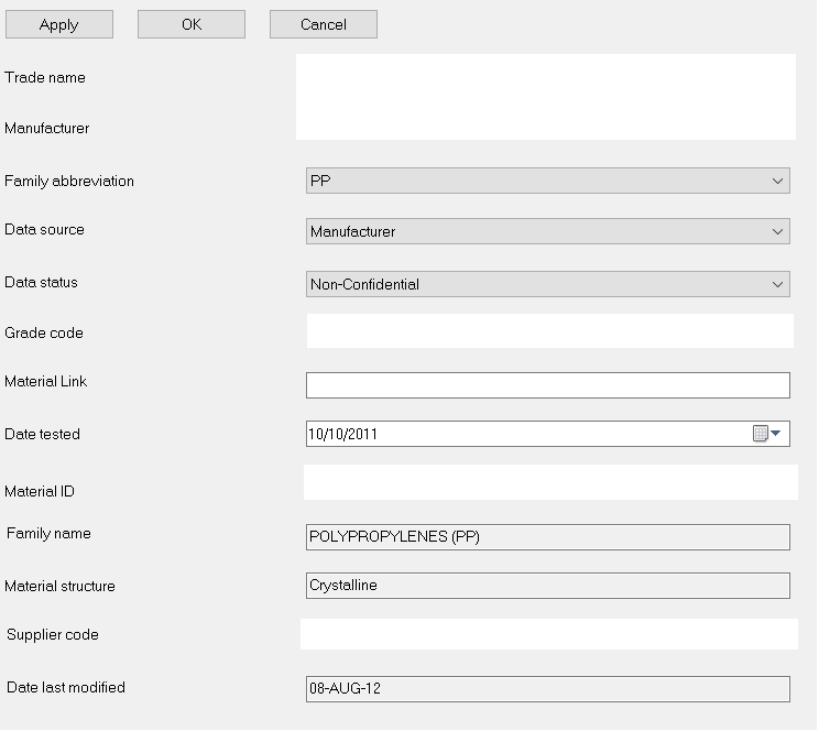
2. General Information
- Complete material information and click Apply
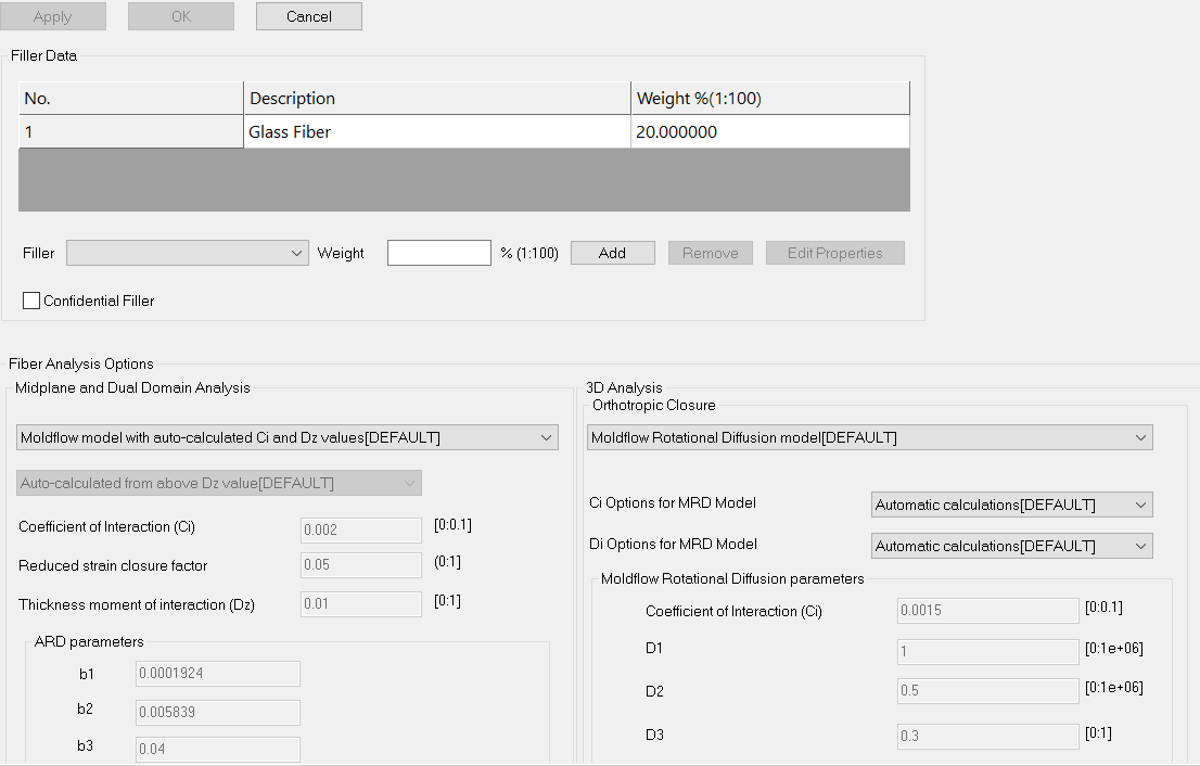
3. Filler
- Complete filler data for filled materials and click Apply
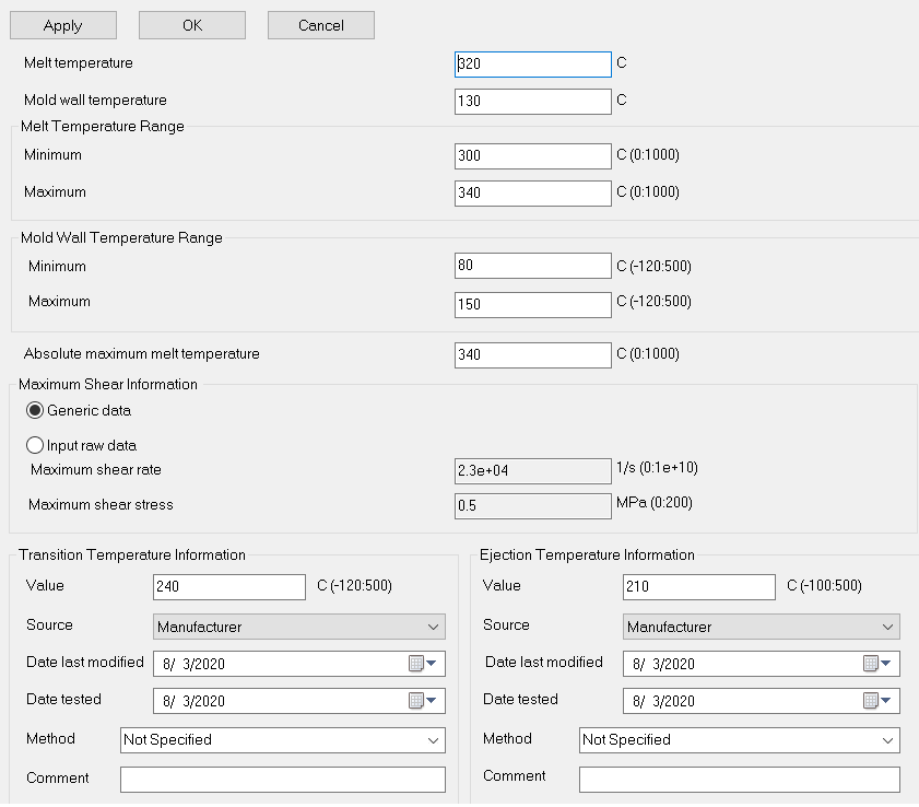
4. Processing and Design
- Complete Melt temperature and range, Mold temperature and range, Absolute maximum melt temperature, Transition temperature & Ejection temperature data and click Apply
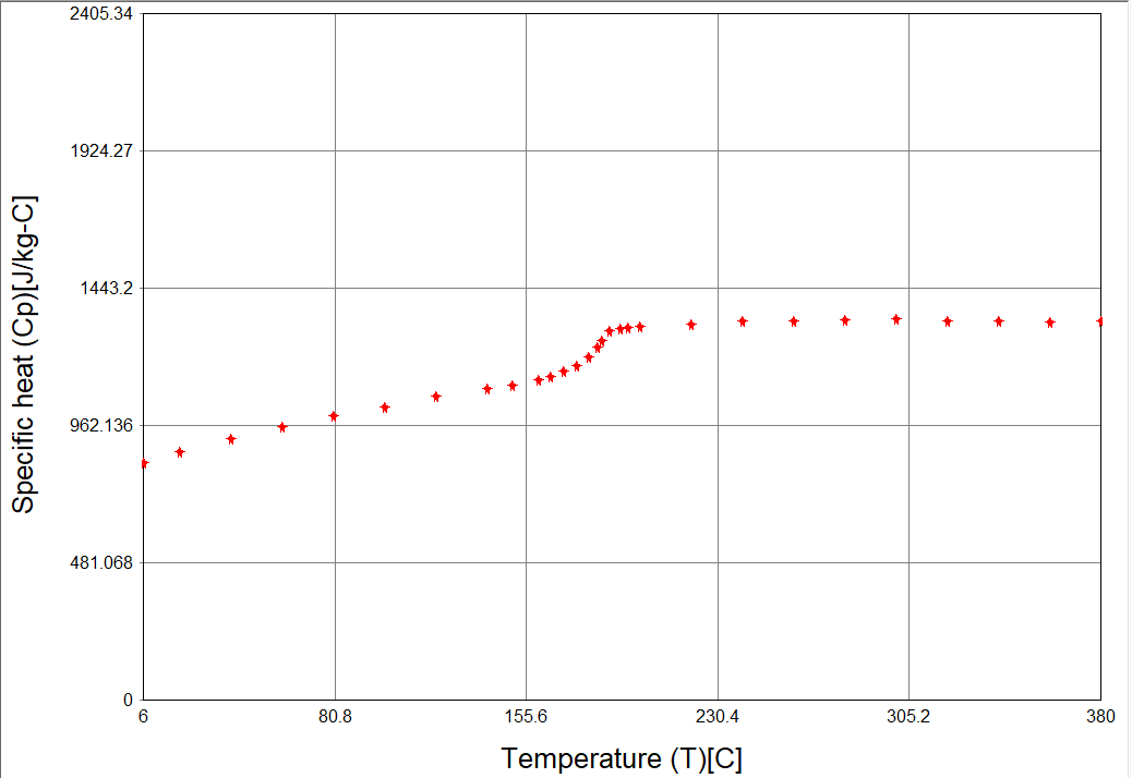
5. Specific Heat
- Upload raw data containing Temperature, Specific Heat & Heating/Cooling rate. Click Apply then Plot to view data
Semi Crystalline grades typically display a sharp peak
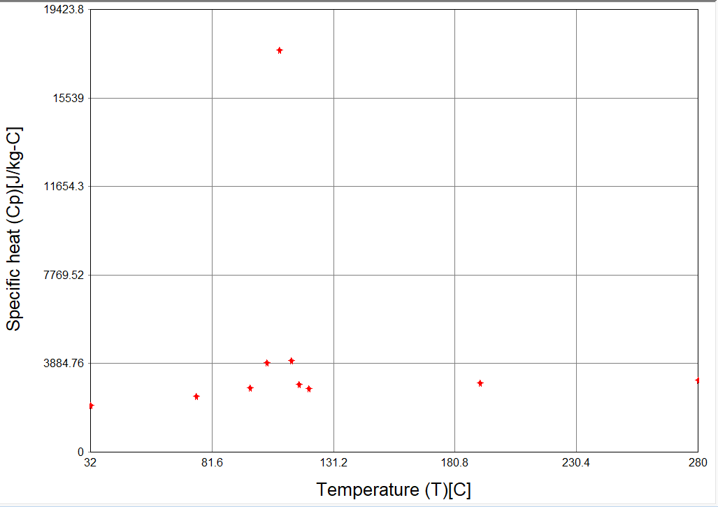
Amorphous grades typically display a smooth transition
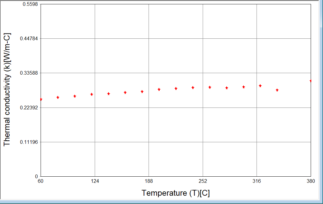
6. Thermal Conductivity
- Upload raw data containing Temperature, Thermal Conductivity & Heating/Cooling rate. Click Apply then Plot to view data
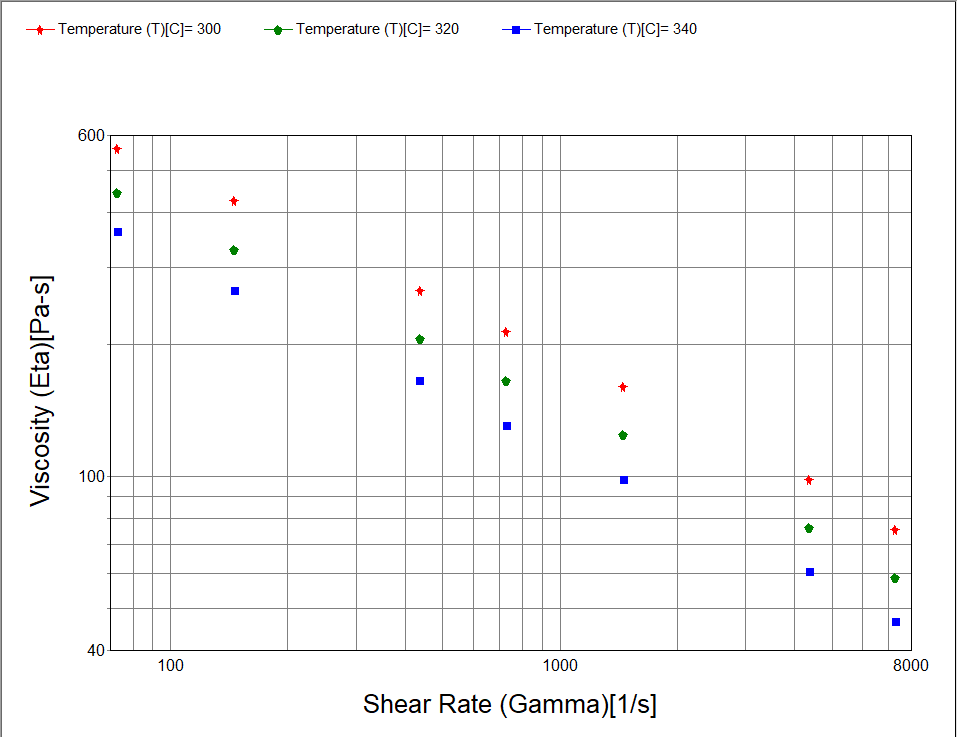
7. Viscosity Input
Choose the type of viscosity input from the following options based on raw data:
- Capillary rheometer data (Temperature, Shear rate, Viscosity, Die Diameter, Die L/D Ratio)
- Slit die rheometer data (Temperature, Shear rate, Viscosity, Slit Height, Slit Width, Slit Length)
- Basic viscosity data (Temperature, Shear rate, Viscosity)
- Cross-WLF Model (no experimental data)
Upload raw data and click Apply then Plot to view data
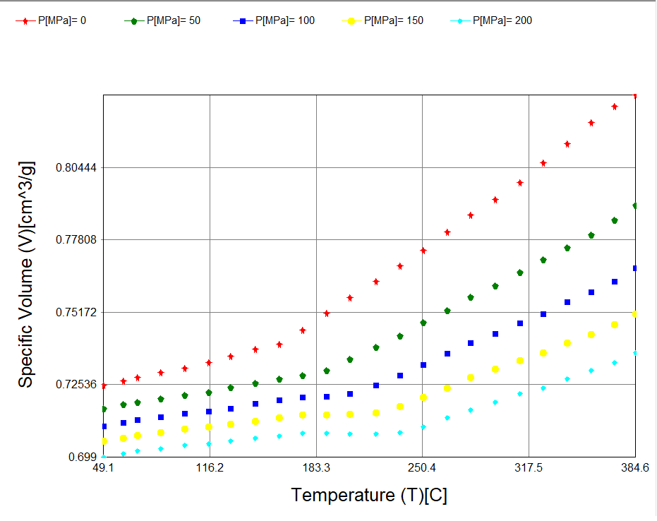
8. PVT Input
Choose Generic PVT data if no experimental data is available
Choose Input raw data and upload data containing Pressure, Temperature & Specific Volume. Click Apply then Plot to view data
Semi Crystalline grades typically display a sharp transition
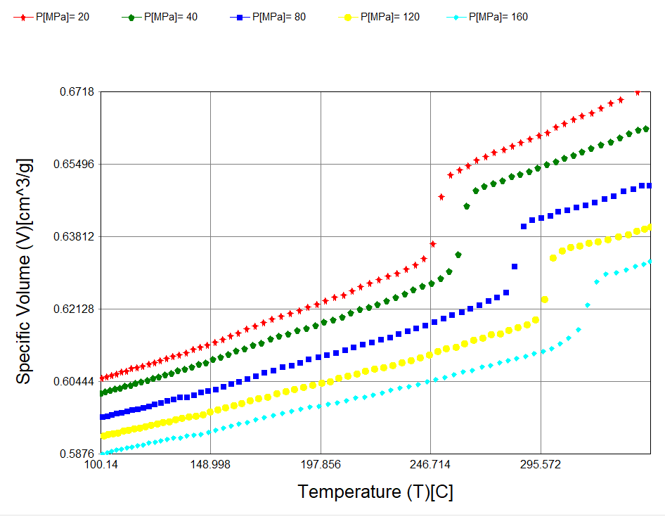
Amorphous grades typically display a smooth transition
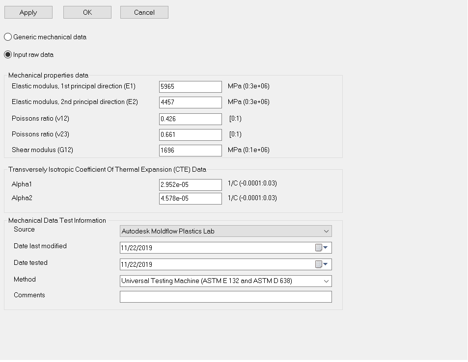
9. Mechanical Input
Choose Generic Mechanical data if no experimental data is available
Choose Input raw data and complete Elastic modulus, Poissons ratio, Shear Modulus & CTE data and click Apply
10. Upload any optional material data
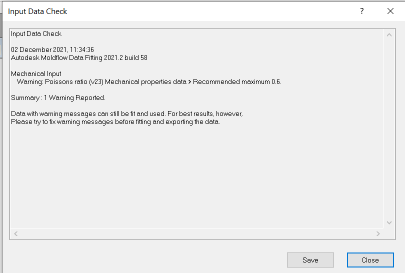
11. Check Input
- Click Check Input to perform data check. Address any errors before proceeding
12. Compute Results
- Click Compute Results to fit the following * models:
- Viscosity Model
- PVT Model
- Ramberg-Osgood Stress-Strain Model (if data is provided)
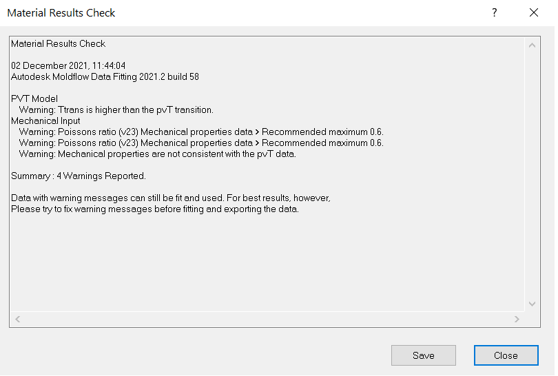
13. Check Results
- Click Check Results to perform data check. Address any errors before proceeding
14. PVT Model
- Click PVT Model and Plot to view the fitted and experimental data
Modifying transition temperature (optional)
- Move the two red X points to match the transition point for the low and high pressure respectively
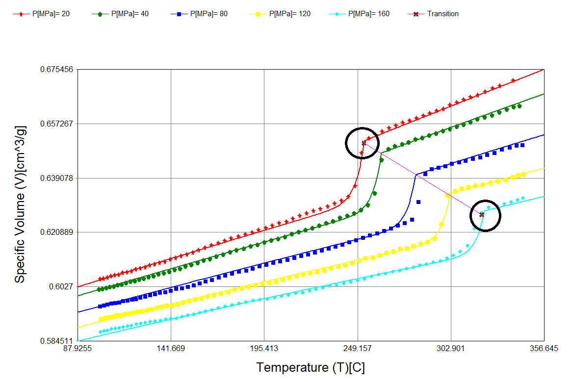
- Right-click and select Refit
15.Viscosity Model
- Click Viscosity Model and Plot to view the fitted and experimental data
Modifying viscoity model (optional)
- Modify coefficients in the Cross-WLF model manually and select the check-box Keep constant fixed for values that should not change during refitting
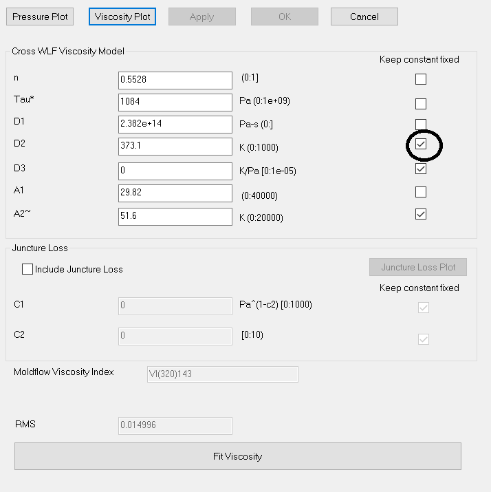
- Select Fit Viscosity to refit data
16. Generate UDB
- Once data fitting is completed, check Generate UDB to create the 21000.udb file for use in Moldflow analysis
Note: AMDF does not support Thermoset datafitting functionality. User should contact the Autodesk Moldflow sales team or datafitting.moldflow@autodesk.com