
To create an Iso reference dimension
- On the ribbon, click Isos tab
 Iso Annotations panelReference Dimension.
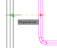
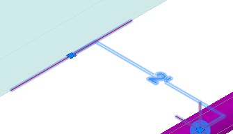
- In the drawing area, use object snap to specify an insertion point on a pipe or fitting.
- Specify the reference object location.
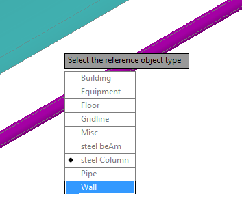
If you snap to a Plant 3D object skip to step 5. Plant 3D objects like equipment, piping, and steel are recognized.
- Specify the reference object type (for example: a Wall).
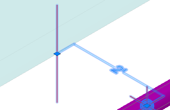
A marker is added inside the pipe and the property palette displays.
- (optional) In the property palette, under Reference Object, enter a Message.
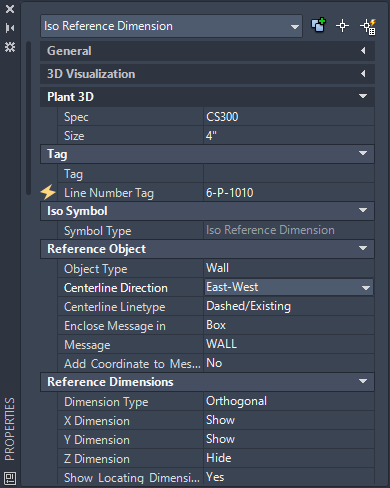
Set other values in the property Palette. For example, you can change the centerline to Up-Down or North-South.
 Up-Down.
North-South.
To view the reference dimension in an Iso drawing
After you have added an Iso reference dimension to piping in the 3D model you can generate a Quick Iso.
- In the drawing area, select piping that has an Iso reference dimension attached.
- On the ribbon, click Isos tabIso CreationQuick Iso.
- Click Create.
After some time, an Isometric Creation Complete balloon message displays.
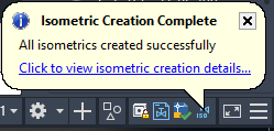
- Click in the balloon to display Isometric Creation results and open the isometric drawing.
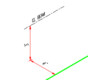
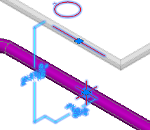
Wall type Iso reference dimension with an X and Z Dimension to an East-West centerline.
To create an Iso reference to structure
- On the ribbon, click Isos tabIso Annotations panelReference Dimension.
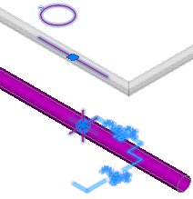
- In the drawing area, use object snap to specify an insertion point on a pipe or fitting.
- Use object snap to specify structure (for example: nearest).
- A marker is added inside the pipe and the property palette displays.
- In the property Palette, under Reference Dimensions, show or hide X Y and Z dimensions.
For example, show Z, show Y, and hide X.
- If the beam centerline orientation is not correct, specify the desired Centerline Direction.