
Use the Probe Path tab > Options panel > Verification Levels option to specify which CAD levels and objects you want to include in collision checking.
Note: This option is available only when creating inspections for CNC and OMV machines.
To specify which CAD levels and objects are included in collision-checking:
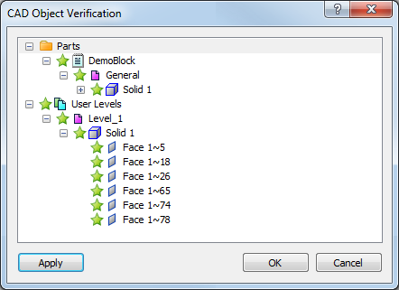
- Click Probe Path tab > Options panel > Verification Levels. The CAD Object Verification dialog is displayed. For example:
- Click
 to expand the folders and display the level and object you want to work with.
 - By default, all CAD levels and objects are checked for collisions. Click the star icon next to a level to include it in or exclude it from verification checks:
 indicates the entry is included in the verification.
 indicates the entry is excluded from the verification.
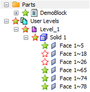
 indicates a parent level that contains a mix of included and excluded entries.
In this example, Face 1~18 and Face 1~26 in Level_1 are excluded from the collision check:
- Click OK to save your changes and close the dialog.
You can also choose which CAD levels and objects are included in the collision-check using the CAD tab.