
Specify calibration positions.
Note: Simple Calibration is available only when creating inspections for CNC machines or manual CMMs.
- Calibrate the probe head.
Note: To create calibration positions in CAD coordinates, calibrate the probe head and probe tool using their nominals, and then create and measure an alignment.
- Select the probe tool in the list of available tools and click the
Calibrate
 button. The
Calibration and Positions dialog is displayed.
button. The
Calibration and Positions dialog is displayed.
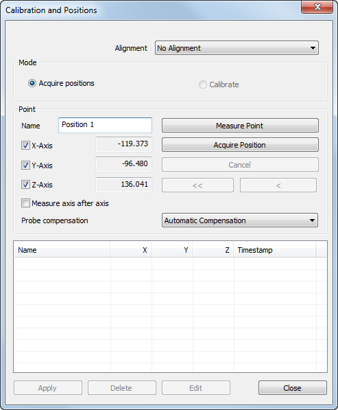
- In the Alignment list, select the alignment in which you want to report the calibration positions. Alternatively, select No Alignment to display and specify positions in machine coordinates.
- Select the Acquire positions option.
- In the
Probe compensation list, specify the direction in which you want to apply compensation for the diameter of the probe. Select:
- an axis to apply compensation along the vector of that axis.
- Automatic compensation to apply compensation along the major axis nearest to the probing direction.
- No compensation to use the position of the probe centre without compensation.
- Enter a Name for the calibration position.
- Specify the location of the calibration position. To create a position:
- by probing a location, click the Measure point button and probe the point. To cancel the measurement without creating a position, click Cancel.
- at a specified location, deselect the X-Axis, Y-Axis, and Z-Axis check boxes, enter the coordinates in the adjacent boxes, and click the Acquire position button.
- at the current location of the probe tip, click the
Acquire position button.
By default, position coordinates are captured with one click. To capture the coordinate for each axis separately, select the Measure axis after axis check box, and probe a point on each axis in turn. The calibration position is located at the intersection of the axes.
When you have created a position, its name and coordinates, and the time at which it was taken are displayed in the position list.
- Repeat steps 5 to 7 to create more calibration positions. To change a point, select its entry in the list, click Edit, and enter new coordinates for the axes.
- When you have created the positions you want to use, you can calibrate the probe or Close the dialog.