
- Click Tools tab > Simulator panel > Dual Column > Machine Position Calibration.
The Calibration Mode page of the Dual Column Calibration Wizard is displayed.
- Select Complete and click Next. The Probing Method page is displayed.
- Select CNC-assisted to measure the calibration items in CNC mode and click Next. The Basic Setup page is displayed.
- In the Anchored to list, select the column you want to use to determine the Machine datum, and click Next. The Definition of Calibration Objects page is displayed.
- Click
 to create the items that you want to use to calibrate the columns. You must specify at least three calibration items and be able to probe each item from both columns.
- When you have specified all the calibration items, click Next. The Default Calibration Sphere Geometry page is displayed.
- Enter the details of the largest sphere with which the columns will be calibrated:
- In the Diameter box, enter the diameter of the sphere.
- In the Stem diameter box, enter the diameter of the sphere's stem.
- In the Direction from the base to the sphere list, specify the vector from the base to the sphere.
- Click Next. The wizard displays a message telling you to switch to column 1.
- Click Next. The Default CNC Settings for Probing Spheres page is displayed.
- Enter the default probing details for the column:
- In the Initial contact list, specify the direction from which you will manually probe the sphere.
- In the Number of points box, enter the number of points to be probed automatically. You must specify at least four points.
- Click Next. The Default Probe Direction for CNC Probing page is displayed.
- Specify the default vector from the probe head hinge point to the stylus tip.
- Click Next. The
Measuring page is displayed. For example:
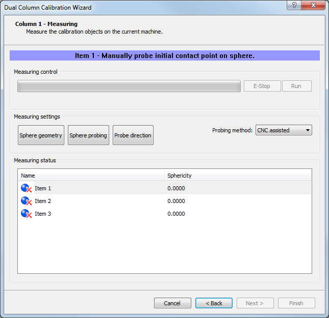
- For each entry in the list of spheres:
- If you want to override the measurement settings for this sphere, click the Sphere Geometry, Sphere Probing, or Probe Direction buttons.
- Manually probe a point on the sphere. The Run button is enabled.
- Click Run to probe the sphere. When probing is complete, the coordinates of the sphere's centre are displayed in the Measuring status list. You can switch to manual probing for individual spheres by selecting Manual in the Probing method list.
- When you have probed all the spheres in the list, click Next. The wizard displays a message telling you to switch to column 2.
- Repeat steps 9 to 14 for column 2, making sure to probe the spheres in the same order as that used for column 1.
- When you have probed all the spheres in the list, click Next. The Result page is displayed.
- The accuracy of the calibration is displayed in the
Deviation box. Click:
- Show Calculated Matrix to display the transformation matrix for the second column.
- Back to reprobe the calibration items if the deviation is outside acceptable limits.
- Finish to accept the results and close the wizard.