
Axis mapping enables you to match the DRO axes to the axes of the measuring device.
Note: The DRO is available only for use with CNC and Manual machines.
To change the axis mapping for the DRO:
- Click Tools tab > Machine panel > DRO.
- In the PowerInspect DRO dialog, click Axis mapping. The Axis mapping dialog is displayed.
- In the Display axis lists, select the DRO axis that corresponds to each CMM axis.
Each display axis can be used only once. If you use an axis more than once, a warning message is displayed when you apply the settings.
- Click Apply to save your changes and close the dialog.
In the following example, the part's Y axis is aligned with the CMM's Z axis; the part's Z axis is aligned with the CMM's Y axis; and the part’s X axis is aligned with the CMM X axis, but in the opposite direction.
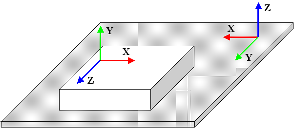
You can correct the values displayed in the DRO using the following axis mappings:
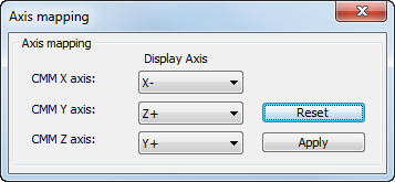
Note: To revert to the original axis mappings, click Reset.