
When you create and measure digitised curves or create curves from wireframes or surfaces of a CAD model, you can use the curves to guide the marking-out of a clay model.
For clay models, marking-out information can help create a copy of the original curve. You can transform and scale the curve to change the model dimensions. Mirroring the curve can create symmetrical guidelines when only half of the original model is available.
You can mark out points and curves. PowerInspect switches to full-screen mode when you mark out.
Marking out points
When you select a point to mark out, the Marking Out dialog displays the distance of the blade from the first point in the curve. The screen shows a line to indicate the distance between the blade and the point. For example: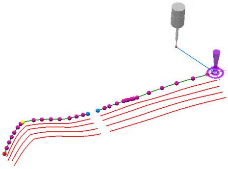
As the blade gets nearer to the point, a series of red bars below the digital read out indicate the proximity of the blade to the mark-out point. When the blade is within the point's tolerance, the indicator bars change to green.
If you select Automatic
 , PowerInspect automatically advances to the next point when the blade is within the tolerance zone of the point.
Marking out curves
The Marking Out dialog displays the distance between the blade position and nearest point on the selected curve, and the screen shows this distance as a line. For example: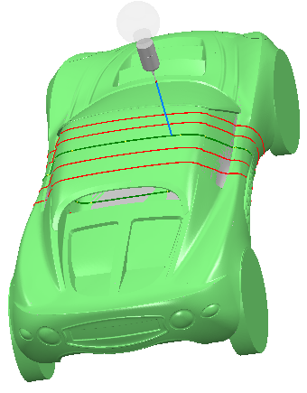
When you select a Curve from CAD Section item that is not split into points, you cannot switch to Mark Out Points mode.
As the blade nears the point, a series of red bars below the digital read out indicate the proximity of the blade to the curve. The bars turn green when the blade is within tolerance.