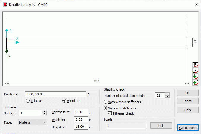
This option enables detailed analysis of the following bars:
- Webs in I-bars,
- Bars with box-section, or
- Channel bars made of rolled or welded sections.
Access the detailed analysis for the French steel code CM66, by clicking the Detailed button in the dialog with detailed results .

The following calculations are defined, based on the requirements described in the CM66 code.
- Stability of web without stiffeners under complex stress (chapter 5,212-3)
- Stability of web with stiffeners under complex stress (chapter 5,212-3)
- Stiffener check (chapter 5,212-4).
The stability check of a web with or without stiffeners is performed separately. The stiffener stability is verified only if the check of web with stiffeners is selected.
The maximum number of analysis calculations points for a single member is 101. An appropriate code condition is checked for every point and for each load case (code combination) defined. The results for the load case with the greatest ratio are displayed .
The top part of the dialog presents a schematic drawing of a member including its dimensions; the bottom right corner of the drawing shows the icons listed below:
|
|
Turns on/off display of stiffeners, stiffener numbers, panel numbers and distances between stiffeners. |
|
|
Turns on/off display of forces acting on the upper flange of a member, their numbers and distances between them. |
|
|
Turns on/off display of forces acting on the lower flange of a member, their numbers and distances between them. |
|
|
Turns on/off display of supports/adjoining bars positioned on the upper flange of a member, their numbers and distances between them. |
|
|
Turns on/off display of supports/adjoining bars positioned on the lower flange of a member, their numbers and distances between them. |
The detailed analysis performed for the French steel code CM66 applies to load cases defined during the calculations. For the current load case or load cases, only the external and internal forces are calculated.
When analyzing a beam, if a support that has already been defined, is detected, it will be drawn automatically in a drawing. If no supports are defined (you are considering a spandrel beam of a frame, for example), a vertical bar (which potentially may act as a support) may adjoin an analyzed beam instead. The points where adjoining (subordinate) beams are positioned are automatically recognized which transfer loads onto the analyzed beam. Positions of concentrated forces acting on the beam are also recognized automatically.
Calculations are started after clicking the Calculations button.
The following options are in the lower part of the dialog:
- Number of calculation points - specify the number of member divisions (into segments of equal length). Internal forces are calculated at these points.
- Web without stiffeners - if this option is selected, then all the options associated with member stiffeners are unavailable. The member is analyzed as the one without stiffeners
- Web with stiffeners - if this option is selected, then the options associated with member stiffeners become available (a part of them, after selecting the Stiffener check option). The member is analyzed as the one with stiffeners
- Stiffener check - when this option is selected, the fields used for the definition of basic stiffener parameters become active; each stiffener can be modified individually.
- Loads - list presenting load cases considered in the member detailed analysis.
Stiffeners are defined automatically after running the Detailed analysis at the following locations on the bar:
- A points where supports have been defined
- At points where concentrated forces are applied
- At points where adjoining bars have been detected.
Parameters of the stiffeners that are defined automatically may be changed: all the stiffeners defined automatically may be freely modified, added or deleted. Stiffener positions are shown in the Positions edit field; a stiffener position may be defined in real coordinates or in relative coordinates (with respect to bar length).
By default, the following stiffener parameters are set:
- Stiffener type - bilateral
- Thickness = web thicknesses
- Width = half the difference between beam width and web thickness
- Height = web height.
It is assumed by default that length of the beam equals the distance between the theoretical axes of members.
The program enables performing the following calculations:
Stability of web without stiffeners under complex stress (5,212-3)
- A beam is being analyzed at the number of points that have been defined by the user in the Number of calculation points edit field
- Stresses at the current calculation point are calculated on the basis of internal forces read for a given load case. These stresses are used further on, to check the empirical verification formula given in point 5.212-3
- Results are presented for each calculation point and for the load case resulting in the most unfavorable ratio.
Stability of web with stiffeners under complex stress (5,212-3)
- The same pattern used for the check of web without stiffeners, is used for the stability of web with stiffeners under complex stress. During verification Robot applies the second empirical formula given in point 5.212-3
Stability of transversal stiffeners (5,212-4)
- The check is run at points where stiffeners are positioned.
- A force acting on the stiffener is calculated, according to the commentary to point 5,212-4, as a difference between the transversal force acting on the point where the stiffener is positioned and the maximum transversal force that a web without stiffeners is able to carry at this point
- Parameters of stiffeners are calculated assuming that they cooperate with the web segment of the length equaling 30-fold thickness of the web.
- Stiffener stability is checked analogously as the stability of columns in axial compression, according to point 3,41 of the code.
