
Apply Dead Loads
Learn how to define and apply self-weight and uniform loads to the structure.
Continue working in your project or open the project Structure-Project-Loads.rtd.
Note: The Tutorial files are located in C:\ProgramData\Autodesk\Examples\Tutorials.In the Standard toolbar, expand the Layouts drop-down menu and select Loads. The layout of the screen changes to display the design, the Load Types dialog box, and the Loads – Case dialog box as shown below.
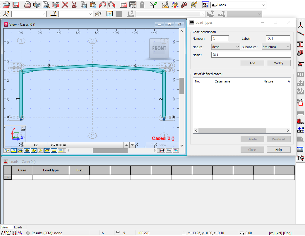
In the Load Types dialog box, in the Case description area, set the Nature to dead, and set its Name to G.
Click Add. The case is added to the Load Type dialog box and the Loads – Case table. It also displays in the Section toolbar in the Cases drop-down menu as shown below. The current units display in the right corner of the bottom comment line.
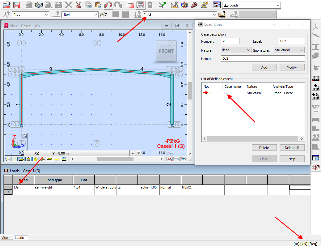 Note: The self-weight load for all of the elements is applied automatically.
In the Menu Bar, select Loads >
 (Load Definition).
In the Load Definition dialog box, on the Bar tab, click
 (Uniform load) as shown below.
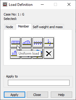
In the Uniform Load dialog box, in the Values area, in the Z field, type (negative) -1.6 and verify that the Coord. System is set to Global as shown below.
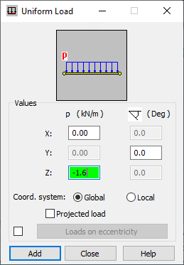 Note: The Z-value corresponds to the total load of the structure (1.6 kN/m). It is set in the global coordinate system as a negative value because it is a gravity load.
Click Add.
Apply the loads as shown below by clicking the bars in the graphical pane. Alternatively, in the Load Definition dialog box, in the Apply to area, enter the bar numbers separated by a space (as shown below), and click Apply.
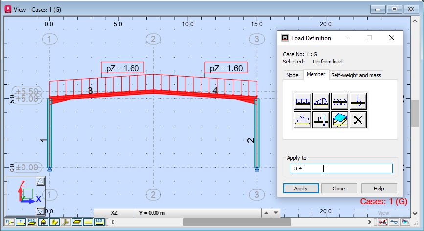 Note: To display the tags for the loads, in the View Control Bar, click
 (Load Value Descriptions).
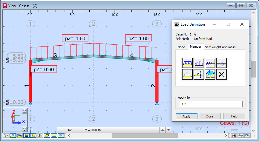
You will now use the same method to add a load to the posts.
In the Load Definition dialog box, on the Bar tab, click
(Uniform Load).In the Uniform Load dialog box, in the Values area, in the Z field, type (negative) -0.6 and verify that the Coord. System is set to Global.
Click Add.
Apply the loads by clicking the posts in the graphical pane. Alternatively, in the Load Definition dialog box, in the Apply to area, enter the bar numbers separated by a space (in this example, use 1 2), and then click Apply.
The loads are represented on the structure as shown below.
Close the Load Definition dialog box.
Save the project.