
Use this dialog to define the parameters of an RC beam.
Access
- Click
Design
 Required Reinforcement of Beams/Columns - Options Code parameters to open the R/C Member Type dialog, and then click
 .
.
- Click
 (R/C Member Type) to open the R/C Member Type dialog, and then click
.
(R/C Member Type) to open the R/C Member Type dialog, and then click
.
Dialog elements
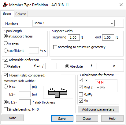
- Member
- Displays the name of the selected member type. The default name is: "Beam" and is assigned the first number available. You can also enter another name in place of the default.
- Span length
-
Contains options that define the calculation length of a beam. There are three ways to define the length:
- At support faces - the distance between the support faces is adopted as a design length.
- In axes - the design length equals the beam length.
- Coefficient, and enter a value - the value becomes the coefficient by which the length at support faces is multiplied to obtain the required value. For example, if you enter a value of 0.25, it means that the required value equals ¼ of the length at support faces. L 0 denotes the beam length between the nodes.
- Support width
- Contains options that define the width of supports. The support width can be defined in two ways:
- Manually - to manually define the support width, enter the required values in the Beginning and End fields.
- According to structure geometry.
If the data concerning support geometry are to be taken directly from the structure model, the according to structure geometry option should be selected. In this case, the support dimensions are calculated on the basis of the projection of supporting element dimensions on the beam axis.
- Admissible deflection
- Defines the maximum deflection calculated according to code requirements for RC beams. It can be defined in two ways.
- Absolute deflection - enter the value of the deflection.
- Relative deflection - the deflection is defined with respect to bar length (e.g. L/200).
If the allowable values are exceeded, the calculation results tables will display.
Note: It is not necessary to define the values of allowable deflection.
- T-beam (slab considered)
-
This option allows to design of RC beams defined as rectangular under the slab as T-beams (beams considered integrally with slabs). If a T-beam (slab considered) is selected, the design of the T-beam is active.
This option influences the cross-section definition and the internal forces.
The edit fields b1 and b2 are available then and you can specify the values of the maximum effective slab widths. They can be defined as the multiplication of slab thickness. The value b1 corresponds to the panel located in the Y+ part of the member, while b2 - in the Y- part. If the beam is placed on the edge of the beam adequate flange width is reduced to zero. No other geometric limitations are taken into account for cross-section definition.
The definition of a beam in the slab is justified if the member lies in the plane of the panel (an offset may be additionally defined for the beam). If the member does not lie in the plane of the panel, then it is assumed that the effective slab width equals zero. Because beams are treated in RC calculation as simple bending or bending with axial force, the symmetrical cross-section is used in RC calculation. The sum of both symmetrical flanges is equal to the sum of the real flange width from the structure. Cross-section based on member cross-section, plate cross-section (thickness), and distance between gravity center (GC) between those two cross-sections. When offsets do not exist GCs are at the same point, then flanges are in the center of the section (is more like a cross-section than a T-section). To create a real T-section the offsets must be equal to half of the distance from the top to the gravity center of the member reduced by half the thickness of the slab.
The internal forces for members are modified by the slab forces from FE. The procedure is described in help topic: Calculations of RC T-beams considered with the slab. Because the calculation of internal forces is based on FE, the area integration (flange width) takes into account the real geometry of the slab including edges and openings.
In this algorithm also option "Simple bending, N=0" is used. If "Simple bending N=0" is selected program automatically try to find width of flange where sum of membrane forces balances out axial forces in the beam typically generated by the offsets. Axial forces in final T-section is reduced to zero or close to zero at the expense of growth of moments. This opion is useful when the beam will be designed as simple bending element. -
Note: T-beams (beams considered integral with the slab) may be defined for two structure types: 3D Shell and Plate; for the remaining structure types these options are not available. Results of RC beam calculations in which a T-beam (beam considered integral with the RC slab) was taken into account, are displayed in the Maps on Bars dialog (the Design tab) and in internal force tables. RC T-beams can also be designed in the RC Beams module.
- Calculations for forces
-
RC beams may be designed for a selected set of forces:
- Axial force Fx
- Bending moment and transversal force My / Fz
- Bending moment and transversal force Mz / Fy
- Torsional moment Mx.
- Additional parameters - click it to view all the codes involving calculation of deflection (for the serviceability limit state). The Additional parameters dialog opens.
- Note - click it display a calculation note.
- Save - click it to add a member type with the defined name and parameters to the list of the formerly-defined RC member types.
Use the buttons at the bottom of the dialog to: