
When the Deformation tab is selected on the Diagrams for Members dialog, the following displays:
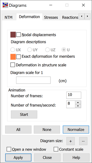
You can select how to display structure deformation because of loads in this dialog.
To do it, use one of the following options:
- Nodal displacement - When selected, structures deformed under loads are displayed. To construct a deformed shape of a structure, the displacements and nodal rotations are considered and third order polynomials (the Hermit polynomial) are used. You can display displacement values in a selected global direction X,Y,Z, or the total value U. Go to the Parameters tab, turn on Diagram Description in the form of labels or text and choose Nodal displacement direction.
- Exact deformation - When selected, structures deformed under loads are displayed. The exact deformation can be displayed only for bar structures. To construct the exact structure deformation, the displacements, nodal rotations as well as the internal forces caused by external loads are considered.
For the quantities listed, you can select the appropriate color and scale.
You can also display displacements from static structure analysis as well as eigen vibration modes from dynamic structure analysis.
You can find the options for animating structure deformation diagrams on this tab. You need to provide 2 parameters to activate the animation: the number of frames created and the number of frames per second. After clicking Start, Robot begins the animation based on the assigned parameters. During the animation, a toolbar displays with options to stop, pause, replay, and so on.
You can save the structure deformation animation to an *.avi file. You can also read and replay the *.avi file in which the structure deformation animation was initially created.
The buttons include the following:
- All - displays the diagrams of all the quantities.
- None - hides the diagrams.
- Normalize - displays the diagram of a selected quantity in such a way that the scale is adjusted to the maximum and minimum value of the highlighted quantity.