
Concrete elements automatically join each other and are represented in the project as a single mass in all views. While joined, you can edit and move the individual elements within their normal ranges and limits.
Valid concrete element combinations that may automatically join with one another include:
- beam to beam
- beam to column
- isolated foundation to isolated foundation
- isolated foundation to wall foundation
- structural floor to beam
- structural floor to column
- structural floor to slab edge
- wall to beam
- wall to column
If the Unjoin Geometry tool is used, automatic joining is disabled for the elements. Use the Join Geometry tool to re-enable automatic concrete geometry joins.
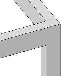
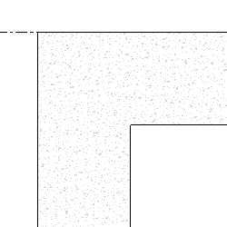
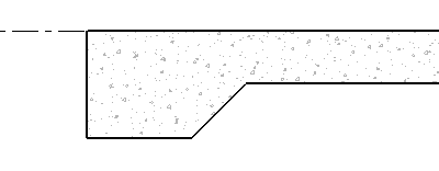
| Examples of joined concrete elements | |||
|---|---|---|---|
| 3D View of 2 beams and a column join | Cross section of a column and beam join | ||
 |
 |
||
| Cross section of a structural floor and slab edge join | |||
 |
|||
- Rectangular sections with a cross sectional rotations of 0, 90, 180, and 270 degrees.
- Trapezoidal, t-shaped, and l-Shaped sections with cross sectional rotations of 0 degrees.
Concrete beams must have either of the following properties to participate in these joins, otherwise they exhibit legacy behaviors and must be manually joined.
- Shape handles are not available for new participating elements.
- Type parameter changes will not automatically update concrete join geometry.
- Concrete elements that are reinforced will also share their cover references in a join.
Other join related restrictions include the following.