
Create beam systems quickly, with one mouse click.
You can place beam systems with one click if the following conditions are met:
- The one-click beam system can only be added in plan or ceiling view with a horizontal sketch plane. If the view or the default sketch plane is not a level and you click Beam System, you are redirected to the Create Beam System Boundary tab.
- There must be a closed loop of supporting elements (walls or beams) already drawn, or the program will automatically redirect you to the Create Beam System Boundary tab.
Note: Curved walls and beams can be used to create a loop, but cannot be the direction defining members in the Beam System.
- Click Structure tab
 Structure panel
 (Beam System).
- Click Modify | Create Beam System Boundary tabBeam System panel
 (Automatic Beam System).
- On the Properties palette:
- Under Pattern, select a Beam Type.
- Under Pattern, for Layout Rule, define the beam system spacing requirements.
- If the beam system will be sloped or uneven in relation to the level, select the Non-planar option.
Note: If you want the walls of the structure in your project to define the slope of the 3D beam system, select Walls Define Slope on the Options Bar. - (Optional) Click Modify | Place Structural Beam System tab Tag panel
 (Tag on Placement) and select either System or Framing as the Tag Style.
- Move your cursor to the structural members where you would like to add the beam system and click to add it.
 Note: The beam system will align its direction parallel to the nearest structural member you selected.
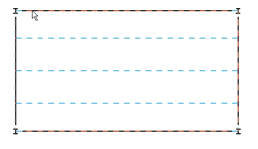
- Add a beam system that spans multiple quadrants. The intersecting beams would not cut the beam system, therefore, any intersections between girders and joists in such a beam system would not display.
- Copy and paste the beam system from quadrant to quadrant if their area, shape, and number of supports differ significantly.
In the example shown above, you should not