The view range is a set of horizontal planes that control the visibility and display of objects in a plan view.
 Video: Use the View Range
Every plan view has a property called view range, also known as a visible range. The horizontal planes that define the view range are Top, Cut Plane, and Bottom. The top and bottom clip planes represent the topmost and bottommost portion of the view range. The cut plane is a plane that determines the height at which certain elements in the view are shown as cut. These 3 planes define the primary range of the view range.
View depth is an additional plane beyond the primary range. Change the view depth to show elements below the bottom clip plane. By default, the view depth coincides with the bottom clip plane.
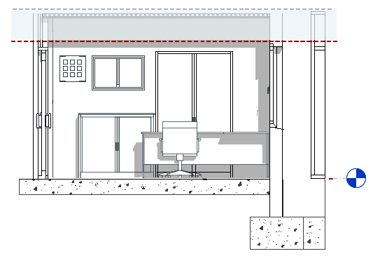
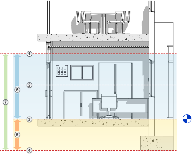
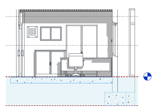
The following elevation shows the view range
 of a plan view: Top
![]() , Cut plane
, Cut plane
![]() , Bottom
, Bottom
![]() , Offset (from bottom)
, Offset (from bottom)
![]() , Primary Range
, Primary Range
![]() , and View Depth
, and View Depth
![]() .
.
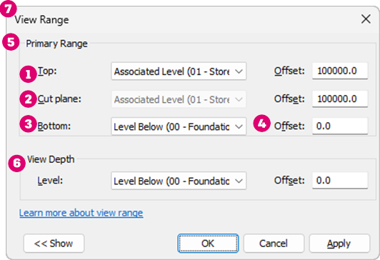
The plan view on the right shows the result for this view range.
|
|
Display of Elements in the Plan View
- Elements outside the view range do not display in the view unless you specify an underlay to show a level outside the view range. For information about the Underlay view property, see View Properties.
- Elements display in the plan view using the cut line weight, the projection line weight, or the <Beyond> line style, according to the rules described in the sections below.
- To change the display of line weights for cut elements and projection elements, use the Object Styles tool.
- To change the display of the <Beyond> line style, use the Line Styles tool.
- Display of elements in reflected ceiling plan (RCP) views is similar to their display in plan views, with the exception that elements are presented as viewed from below and mirrored.
Elements Intersected by the Cut Plane
In a plan view, Revit uses the following rules to display elements that are intersected by the cut plane:
- These elements are drawn using the cut line weight of the element category.
- When the element category does not have a cut line weight, the category is not cuttable. The element is drawn using the projection line weight.
Exceptions for the display of elements intersected by the cut plane include the following:
- Walls shorter than 6 feet (or 2 meters) are not cut, even if they intersect the cut plane.
The 6 feet (or 2 meters) are measured from the top of the bounding box to the bottom of the primary view range. For example, if you create a wall whose top is 6 feet above the bottom clip plane, the wall is cut at the cut plane. When the top of the wall is less than 6 feet, the entire wall shows as projection even where it intersects the cut plane. This behavior always occurs when the Top Constraint property for the wall is specified as Unconnected. If the top constraint property of the wall is specified as Connected, then the cut plane position is always used to define if the wall is cut or projected.
- For some categories, individual families are defined as cuttable or non-cuttable. If a family is defined as non-cuttable and its elements intersect the cut plane, they are drawn using the projection line weight. See About Non-Cuttable Families.
Tip: Families can include geometry that intersects the cut plane, allowing the geometry to be visible when above the cut plane.
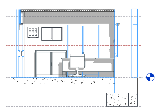
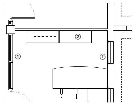
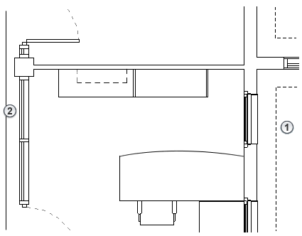
In the following elevation, blue highlighting indicates elements that intersect the cut plane.
The plan view on the right shows the following:
![]() Elements that are drawn using the cut line weight. (walls, door, and window)
Elements that are drawn using the cut line weight. (walls, door, and window)
![]() Elements that are drawn using the projection line weight because they are non-cuttable (casework).
Elements that are drawn using the projection line weight because they are non-cuttable (casework).
|
|
Elements Below the Cut Plane and Above the Bottom Clip Plane
In a plan view, Revit draws these elements using the projection line weight of the element category.
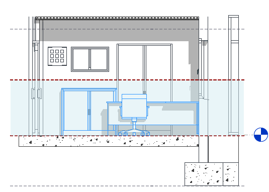
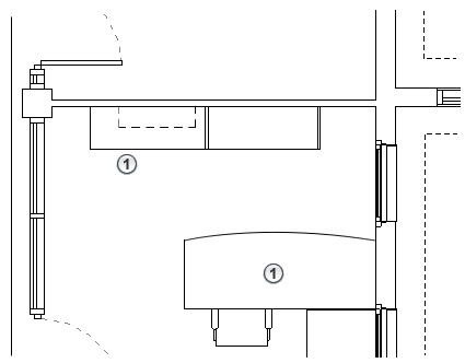
In the following elevation, blue highlighting indicates elements that are below the cut plane and above the bottom clip plane.
The plan view on the right shows the following:
![]() Elements that are drawn using the projection line weight because they are not intersected by the cut plane. (cabinet, desk, and chair)
Elements that are drawn using the projection line weight because they are not intersected by the cut plane. (cabinet, desk, and chair)
|
|
Elements Below the Bottom Clip Plane and Within the View Depth
Elements within the view depth are drawn using the <Beyond> line style regardless of the element's category.
Exceptions: Floors, structural floors, stairs, and ramps located outside the view range use an adjusted range that is 4 feet (about 1.22 meters) below the bottom of the primary range. Within this adjusted range, the elements are drawn using the projection line weight for the category. If they exist outside this adjusted range but within the view depth, these elements are drawn using the <Beyond> line style.
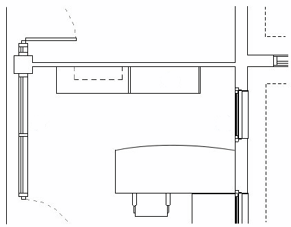
For example, in the following elevation, blue highlighting indicates elements that occur below the bottom clip plane and within the view depth.
The plan view on the right shows the following:
![]() An element (foundation) within the view depth that is drawn using the <Beyond> line style.
An element (foundation) within the view depth that is drawn using the <Beyond> line style.
![]() An element that is drawn using the projection line weight for its category, because it meets the exception conditions.
An element that is drawn using the projection line weight for its category, because it meets the exception conditions.
|
|
Elements Above the Cut Plane and Below the Top Clip Plane
These elements are not displayed in a plan view unless their categories are window, casework, or generic model. Elements in these 3 categories are drawn using the projection line weight as viewed from above.
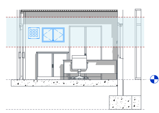
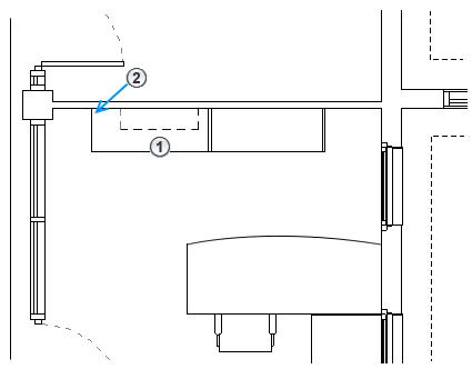
For example, in the following elevation, blue highlighting indicates elements that occur between the top of the view range and the cut plane.
The plan view on the right shows the following:
![]() Wall-mounted casework that is drawn using the projected line weight. In this case, the dashed line style for projection lines is defined in the casework family.
Wall-mounted casework that is drawn using the projected line weight. In this case, the dashed line style for projection lines is defined in the casework family.
![]() The wall sconce (a lighting category) that is not drawn in the plan because its category is not window, casework, or generic model.
The wall sconce (a lighting category) that is not drawn in the plan because its category is not window, casework, or generic model.
|
|
View Range in a Reflected Ceiling Plan (RCP)
Like plan views, reflected ceiling plans also have a view range setting but with some differences.
- A reflected ceiling plan's view direction is up from the cut plane.
- A reflected ceiling plan includes the cut plane as part of the primary range, but it is typically positioned above the cut plane of a plan view. Cut planes in a reflected ceiling plan are often set above the head height of the doors and windows.
- The area between the cut plane and the top of the view range establishes the primary view range of the view. The bottom setting of the view range is not used in a reflected ceiling plan. Elements falling in the primary view range will use the projection line weight.
- View depth is established in the up direction from the cut plane. Elements not in the primary view range but within the view depth will use the <Beyond> line style.