To create a sloped surface, draw a slope arrow or edit the properties of the boundary lines of the surface.
Edit the boundary of the element in a plan view or a 3D view. Then use one of the following methods:
- Slope arrow: Draw a slope arrow on the element. Use slope arrow properties to further define the slope.
- Boundary line properties: Define the slope of the surface by changing properties of its boundary lines.
How slope properties are measured
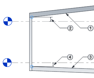
Slope-related properties are measured from the bottom face or top face of the element, depending on the type of element:
- For roofs, ceilings, and soffits, slope-related properties are measured from the bottom face.
 For example, Height Offset From Level specifies the distance between the level and the bottom face of a roof.

- For floors, toposolids, and structural floors, slope-related properties are measured from the top face.
 For example, Height Offset From Level specifies the distance between the level and the top face of a floor.

Modeling multiple slopes
With the exception of roofs, elements can slope in one direction only. To create a surface with multiple slopes, create multiple elements, each with its own slope. Then align and lock the elements together.
For floors, structural floors, and roofs, you can also use shape editing tools to split a surface into subregions that slope independently. See About Editing Floor and Roof Shape.
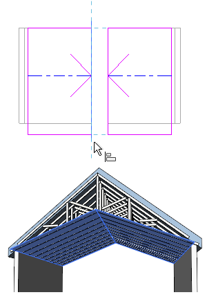
Example
The following images show a cathedral ceiling consisting of 2 surfaces, each with its own slope.