
Learn how to place single or multiple rebar bending details on your reinforcement drawings.
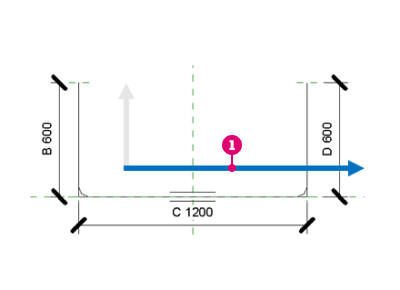
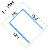
To place realistic bending details
- In the Annotate tab
 Symbol panel, click
 (Bending Detail).
- Select
(Realistic) from the Modify | Place Bending Detail tab Type panel.
- Select one rebar set.
- Select the Tag Position from the properties palette or press Space bar to cycle between the options.
- Click to place the bending detail.
OR
- Select one rebar set and in the Modify | Structural Rebar contextual ribbon Symbol panel, click
(Bending Detail).
- Make sure Realistic is selected in the type panel.
- Click to place the bending detail.
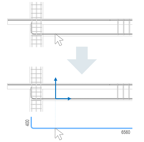
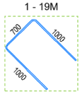
 (Align to Bar) option from the Modify | Place Bending Detail contextual ribbon Mode panel, and align the bending detail in the vertical or horizontal direction with respect to the selected rebar. The point clicked when selecting the rebar is used as a reference for aligning the bending detail.
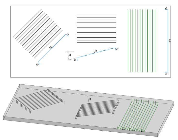
To place multiple realistic bending details
- Select two or more rebar sets.
- In the Modify | Structural Rebar contextual ribbon Symbol panel, click
(Bending Detail).
OR
In the Annotate tab
Symbol panel, click
(Bending Detail) and toggle the Multiple Selection option and select two or more rebar sets.
Note: Click a bar to add to the selection, click again to remove. Use Ctrl+ window or crossing window to add more bars to existing selection and hold Shift to remove multiple bars. - Click to place the bending details.
The bending details are placed in the same relative position as the selected rebar. After placing them, you can select the bending details and move or nudge them as required. The middle point of the bounding box containing all the selected rebar is used as the alignment point.
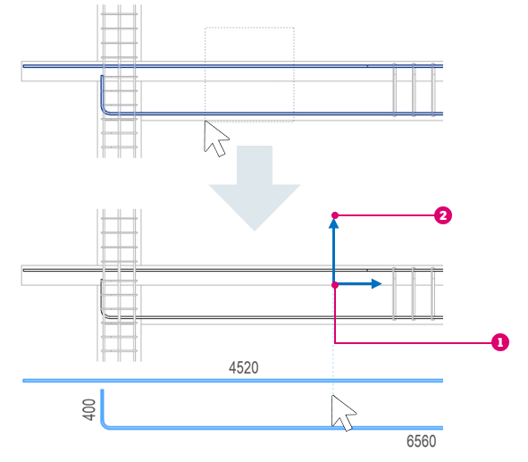
 Center point of the bounding box for all the selected rebar.
 Aligned to the X and Y directions.
Parallel to View
Use this option to filter out any bars that are not parallel to the view, during placement. This way, you can select only the bars that have the bar plane parallel to the view plane.
- In the Modify | Place Bending Detail contextual ribbon Mode panel, click
 (Parallel to View).
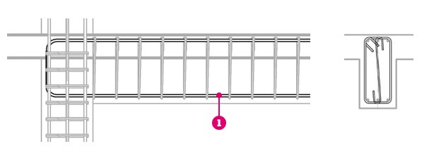
Bars that are parallel to the view.
Bending Detail Orientation
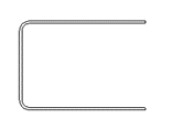
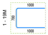
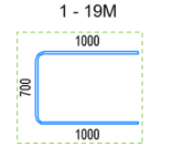
Bending details are oriented in the same way as the host rebar when the rebar bar plane is parallel to the view plane.
| Rebar (parallel to view) | Bending Detail - Angle 0° | Bending Detail - Angle 30° |
|---|---|---|
 |
 |
 |
You can rotate the bending details using the rotate command or change the Angle parameter in the properties palette.
When the bar plane is perpendicular to the view, which would be the case for slab reinforcement in a reinforcement plan, the bending details are oriented as if the set was cut, and the section rotated up (i.e., looking from the bottom of the view) or to the left (i.e., looking from the right).
The bar rotation in its bar plane is also taken into account by the bending detail.
Tag Alignment in Realistic Bending Details
The tag is embedded in the realistic bending detail and can be aligned to the horizontal direction of the rebar shape family, or according to the view.
The alignment is controlled by the Tag Alignment parameter.
| Rebar in Project | Rebar Shape Family | Tag Alignment - Rebar Shape Family, Tag Position - Top | Tag Alignment - View, Tag Position - Top |
|---|---|---|---|
 |
|
 |
 |
 |
 |
 |