
Define Beam Loads
Description
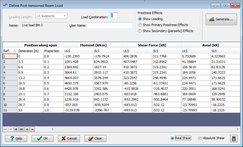
This form controls the definition of loadings on the beam.
The sign convention for bending moments is:
+ve : sagging
-ve : hogging
The direction in which the bending moments are plotted may be changed from the Graphics tab on the Preferences form.
The loads defined in the table are displayed graphically. By default the bending moment and shear force diagrams are shown. The bending moment and axial load plot may be shown by clicking in the axial load column of the table.
Outline Procedure
This form may be accessed by selecting the Design Beam Group button in the Explorer Navigation Pane. If the required load is already defined then click on the name of the required load item. If a new load is required, then (i) select the design beam top node or Beam Loads item, (ii) click on the Add button on the Navigation Pane's Toolbar and (iii) select the appropriate load from the sub menu.
In the analysis, any differential temperature loadings defined here will be combined with the other loads defined as loading combination 3 if they are adverse.
Settlement of support loadings will be included when required by the code, and will be taken as either positive or negative, whichever is adverse.
Soil pressure loadings and superimposed dead loadings may have more than one case defined. When the beam analysis is carried out the program automatically selects the critical case.
The values of the loads along the beam are then entered in the table. For details of the table features, and navigation, see the help topic Table Features & Navigation.
Alternatively, the loadings may be either:
imported from a JSON or an ASCII text file by clicking on the Import Loads button. The format of the ASCII text file is described in the Beam Loading Data topic. (Refer to the note below for multi-span beams).
generated from a series of uniform trapezoidal applied loadings via the Generate button.
Loading types appended with an asterisk in the Toolbar Add sub menu can be defined multiple times, allowing both enveloped effects and non-enveloped effects, for example, to be included in the same Design Beam.
Normally two cases will be appropriate for soil pressure load or a superimposed dead load - either extreme maximum and extreme minimum, or with maximum and minimum load factors applied. When the beam analysis is carried out the program automatically selects the critical case.
Where multiple load cases of the same type are included in the data file, the User Notes facility is a useful tool to record additional details of the load case contents. A user name can be entered, which will get appended to the load name in the data report and results.
Post-tensioned multi-span beams - particular features
The Prestress Effects panel will be visible for Post_tensioned beams only.
For Post_tensioned beams, if the load data is entered by importing from an ASCII text file, the data will be generated for all spans, although the table displays the information for a single span at a time.
Form Graphic
Related Topics
Generate from Applied Trapezoidal Loads