
Beam Eccentricities
Description
In most cases the ends of a member are located exactly at the corresponding joints. However, it is possible to specify that the end of a member is at a distance from the joint, but rigidly connected to it. An eccentricity is the distance from the joint to the end of the member.
This form is used to define members whose ends are eccentric from the reference joints defining the member. The eccentricity can be expressed with respect to either local or global axes. A stud of infinite thickness is assumed to connect the member to the joint.
Each row of the table defines the eccentricity that will be applied to a group of members. The display shows all members initially drawn in green. When the current eccentricity is assigned to a member it is drawn in red. When an eccentricity has been assigned in the current form, but that eccentricity is not the current eccentricity, the member is drawn in purple. When an eccentricity has been assigned in another form the member is drawn in grey. In this context, the current eccentricity is the eccentricity defined in the row of the table which currently contains the cursor.
When eccentricities have been defined the cursor may be moved up and down the table to switch the member colours from purple to red, to identify the members to which a given set of section eccentricity data has been assigned.
When an eccentric member is specified, member loads are applied along the eccentric member, and not along the line connecting the two nodes. Note that the length of the eccentric member may not be the same as the distance between the two reference nodes.
Where a member release coincides with an eccentric end to a member, the release is applied at the joint end of the rigid stud which provides the eccentricity.
Local and global eccentricities may be applied to the same end of a member. In this case the eccentricities are added in the same way as a series of vectors would be added.
Outline Procedure
This form may be accessed by selecting the Structure Definition Group Button in the Explorer Navigation Pane. If the required group of beam eccentricities is already defined then click on the name of the required 'Beam Eccentricities' Active Group Item. If no beam eccentricities have been defined, or if a new set of beam eccentricities is required, then (i) ensure that the Active Group Item is not in a Sub Model, (ii) click on the Add button on the Navigation Pane's Toolbar, (iii) select Advanced Beam Set from the drop-down menu and (iv) select Eccentricities from the sub-menu.
For details of the table features, and navigation, see the help topic Table Features & Navigation.
Create a new row in the table using the +(Insert Record) button.
Specify the required eccentricity details in the new row (at least one eccentricity must be specified).
In the field labelled 'Graphic Pick Mode' select the appropriate type of beam to which the eccentricity data in the new row is to be applied (e.g. 'Longitudinal Beam' will apply it along all the beam elements in a selected longitudinal beam). This is to assist when using boxes to select the members.
Selection is now carried out with the mouse on the display area. Either:
- Point with the mouse to a single member of the type defined in the 'Pick mode' field, and click. The member will turn red, indicating that the current eccentricity has been applied, or
- Use the mouse to box around a group of members on the display. All of the boxed members which are of the appropriate type will have the current eccentricity applied, and will be drawn in red. .
As each beam is selected the assignment controller will add it to the list of assignments for the eccentricity of the current row. Alternative selection methods are available in the assignment controller.
The name of each set may be modified.
The members defined as eccentric may be shown in the graphics window in their eccentric location by toggling visibility for 'Beam eccentricities' in the 'Graphic Objects Toolbar'.
If multiple construction stages have been defined then member eccentricities may be changed between stages as described in Beam Releases and Beam Eccentricities at Stage.
Special Mouse Actions
Eccentricities applied to a single member can be deleted by setting the Select mode to 'Remove' on the graphics window toolbar.
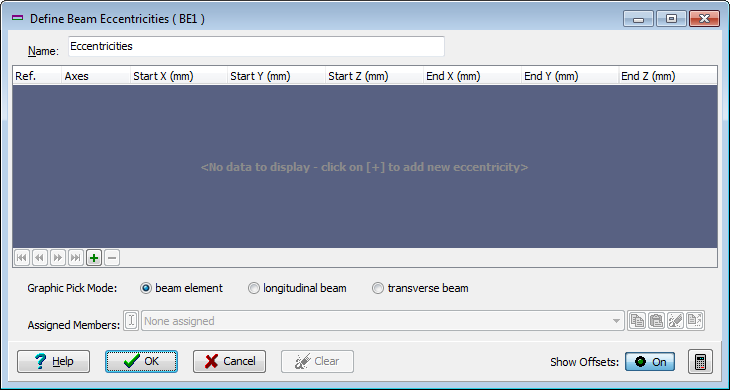
Form Graphic
Field Help
Name
The initial default name may be edited to identify this set of beam eccentricities. The name will appear for example in the Data Reports printout. In the Explorer Navigation Pane active group item description the name is prepended by a short reference acronym that is automatically generated and cannot be edited.
Ref.
Display only - not editable
Axes
The direction and distance from the joint to the end of the member can be expressed with respect to either local or global axes according to the selection made here.
Start X, Y, Z
End X, Y, Z
The eccentricity is the distance from the joint to the end of the member. Note that when an eccentricity is specified, the length of the member is not necessarily the distance between the start and end nodes, and the local axes of the member are not necessarily the same as those of a member between the same joints but with no eccentricity. Different eccentricities may be specified at either end of the member. The eccentricity entered at the start end will automatically be applied to the other end, but may then be changed if required.
Note that the program may have difficulty calculating the orientation of a member if an eccentricity specified with respect to LOCAL member axes greatly alters the orientation. The local y or z eccentricity cannot be greater than the length of the member, and an error message will be issued when a member is selected if this occurs.
Graphic Pick Mode
This field defines the pick mode when selecting individual members or groups of members with the mouse. The available selections are:
| Pick Mode | Description |
|---|---|
| Longitudinal Beam | Only the longitudinal members selected by the mouse will have the current member eccentricity set assigned. |
| Transverse Beam Member | Only the transverse members selected by the mouse will have the current member eccentricity set assigned. |
| Any Beam | Any beam member selected by the mouse will have the current member eccentricity set assigned. |
Assigned Members
List of members to which the current parameters have been applied in the assignment controller.