
Transfer Results
Description
To access this form select Calculate | Transfer Results from the Main Menu. This form is used to select the result transfer location and map the load cases from the structural analysis to the load effects cases required for the design and code checking. Structural analysis result transfer can be to a Design Section or a Design Beam. The selection and load case mapping forms a transfer set. Multiple sets can be created.
Outline Procedure
For Beam and Virtual Member transfer type:
Set the Transfer Type to Beam or Virtual Member. Point to the required beam or virtual member, and click to select it. Virtual member selection is only a valid selection option for refined analysis models with virtual members defined.
The drop-down list labelled Virtual member can be used to select the virtual member non-graphically.
The selected beam or virtual member will be highlighted. When the design beam is a multi-span type, the member selected should be a member corresponding with the first span of the design beam. Clicking again on another beam will de-select the current beam, and select the new one. The details of the selected design item are shown on the form.
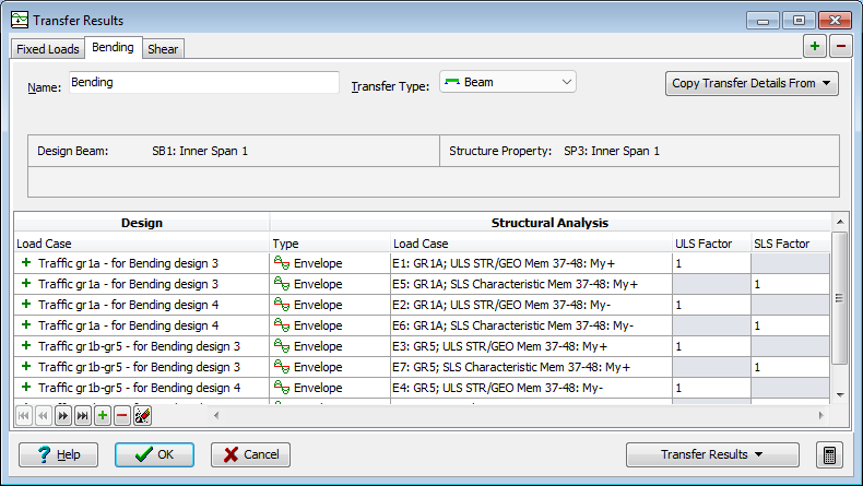
The left-hand side of the table lists the load effect cases required for the code checking of the design beam. The right-hand side lists the load cases from the refined analysis or the line beam analysis. For a given row of the table, the moments and forces resulting from the load case specified on the right-hand side will be transferred as load effects for the design and code checking load case specified on the left-hand side.
For Section transfer type:
Set the Transfer Type to Section. Point to the required beam element assigned to a Design Section, and click to select it. Select the Start or End field item for the chosen beam element. The selected beam element end will be highlighted. Clicking again on another beam element will de-select the current selection, and select the new one. The details of the selected design item are shown on the form.
The left-hand side of the table lists the load cases from the refined analysis or the line beam analysis. The right-hand side of the table lists the load effect cases required for the code checking of the design section. For a given row of the table, the moments and forces resulting from the load case specified on the left-hand side will be transferred as load effects for the design and code checking load case specified on the right-hand side.
For all transfer types:
The procedure is therefore to set up a table of the corresponding load case data sets for the specified location. To create additional transfer sets, click on the add tab button (top-right corner of form). Selection and table details can be copied from another set using the Copy Transfer Details From button. There is no persistent link between the new and copied set.
Once the transfer sets have been defined use the Transfer Results drop down button to complete the transfer. The options depend on the currently active transfer set.
| Item | Description |
|---|---|
| Transfer All Sets | This transfers the load effects, for each defined transfer set in turn, to the associated design section or beam and presents a report summarising the action. |
| Transfer Current Set to Design Beam | For Beam and Virtual Member transfer types, this transfers the load effects directly to the associated design beam for code checking. |
| Transfer Current Set to Design Section | For Section transfer type, this transfers the load effects directly to the associated design section for code checking. |
| Transfer Current Set to Linked File | This transfer the load effects to the existing design beam or section file when the associated design object is linked to the project. |
| Export Current Set... | The application will prompt for a transfer file name to which the load effects will be written, and from which they may later be read in to a design beam or section in this or another project. |
For Beam and Virtual Member transfer types, prior to transfer, the load effects are multiplied by the factors specified under the appropriate limit state columns of the table. For further details on these, refer to the field help.
The design beams allow multiple load cases for some of the design load types, namely surfacing (allowing different load factors to be applied), soil pressure loading, and variable action cases. Refer to the field help for the design load case.
For Section transfer, the load effects are un-factored when transferring analysis load cases, or factored if transferring compilations or envelopes of compilations.
Choose either a "New Load" or an existing load when mapping for transfer to a design section. More than one analysis load case can be transferred to a new or existing section load case.
Property Set Envelopes
Structural analysis Property Set Envelopes are used to obtain critical effects for members with the same structural properties. For example, design section code checking on a number of identical piles or design beam checking for all internal longitudinal beams in a deck.
Select any beam (or beam element for Section transfer) assigned to the structural property of interest and select the corresponding analysis property set envelope in the transfer table. For design sections, an effect also needs to be specified in the transfer table. On transfer, the extreme maximum or extreme minium value (depending on the specified scope of the envelope) for the matching effect will be calculated using all results for all beams (or beam elements) with matching structural property, along with the associated effects.
Form Graphic
Field Help
Name
Enter an alternative name for the transfer set.
Transfer Type
Set the Transfer Type to Section, Beam or Virtual Member. Virtual member selection is only a valid selection option for refined analysis models with virtual members defined.
Start/End (Section Transfer)
Set the Start or End of the selected beam element position required for transfer to a Design Section. The graphics will show the selected end. This field box will have no effect if transferring Property Set Envelopes since the member end results are enveloped.
Consider Adjacent Inline Element When Processing (Section Transfer)
For Section transfer type only, checking this box will consider the most inline beam element adjacent to the selected beam element when computing the results (moments will be averaged at the beam element end, and the maximum force taken). Checking this box will have no effect if transferring Property Set Envelopes since the enveloped result in each element will be identical.
Virtual Member and Method
Virtual Member selection and Calculation Method drop downs are available if the transfer type is set to Virtual Member.
Permanent Value (Section Transfer)
For permanent load transfer, the ultimate gamma factor applied will be according to the unfavourable or favourable selection made here. For transfer of compilations, this selection is not used since the gamma factor is determined from the compilation definition.
Design: Load Case (Section Transfer)
To transfer to a new design section load case, select an item from the list which has a ![]() icon. To transfer to an existing design section load case, select an item which has a
icon. To transfer to an existing design section load case, select an item which has a ![]() type icon. If a new design load case selection is made, then another new design load case option is added to the selection list. Result transfer to an existing design load case will append to the existing load details.
type icon. If a new design load case selection is made, then another new design load case option is added to the selection list. Result transfer to an existing design load case will append to the existing load details.
Design: Load Case (Beam Transfer)
The drop-down list contains all the load effect cases which are appropriate for the current structure type, and beam of the type currently selected, for transfer of load data.
Select the loading case for which data is to be extracted from the analysis results.
To transfer to a new design beam load case select an item from the list which has a  icon. To transfer to an existing design beam load case select an item which has
  type icon. If a new design load case selection is made and it is a multiple load case type (namely superimposed dead loads, surfacing, soil pressure loading, and all live load variable action cases) another load case of the same type with an incremented identifier will be available in the selection list. Result transfer to an existing design load case will overwrite the existing load details.
Results will be accumulated when two or more rows of the table are set up so that they will return analysis results to the same beam design load case. This ensures that construction sequence loading can be transferred correctly for a series of analysis construction stages. This action also facilitates transfer to Ultimate Limit State 'Design' load effects from one 'Analysis' load case, and the corresponding Serviceability Limit State 'Design' load effects from another 'Analysis' load case.
If the loading case selected is for group 1a traffic this will appear in the beam data split into its component parts (TS, UDL, footway).
Design: Combination (Section Transfer)
Select from the following combination types:
- SLS Characteristic
- SLS Frequent
- SLS Quasi-Permanent
- ULS Persistent/Transient - Set A
- ULS Persistent/Transient - Set B - Eqn. 6.10
- ULS Persistent/Transient - Set B - Eqn. 6.10a
- ULS Persistent/Transient - Set B - Eqn. 6.10b
- ULS Persistent/Transient - Set C
- ULS Accidental
- ULS Seismic
For 'ULS Persistent/Transient' the Set defines which of EN1990: Annex A2: Table A2.4(A), Table A2.4(B) or Table A2.4(C) is applied, and which of the equations referred to in Table A2.4(B) is applied.
The selection made in this field determines the 'Category' and the 'Action' that are available in the next columns.
Design: Category (Section Transfer)
Select from the drop-down list, whose content corresponds to the definitions in EN1990:Cl.4.1.1 for the 'Combination' selected. These options are defined in detail in EN1990: Annex A2 Table A2.4(A), A2.4(B), A2.4(C),A2.5 and A2.6 for bridges, or in the appropriate corresponding National Annex document.
Categories available are:
| Type | Description |
|---|---|
| Permanent | for permanent actions (dead, superimposed dead, etc). |
| Var - Leading | for the leading variable action. |
| Var - Other | for the accompanying variable actions in SLS. |
| Var - Accom - Main | for the accompanying variable actions in ULS. |
| Var - Accom - Other | for the accompanying variable actions in ULS. |
| Seismic | for seismic actions in ULS. |
| Leading Accidental | for the leading accidental action in ULS. |
The information supplied here will be used to apply the appropriate combination factors.
Design: Action (Section Transfer)
Select from the drop-down list, whose content corresponds to the selected Bridge Type and 'Category' selection.
Design: Name (Section Transfer)
Optionally, enter a name which will be appended to the section load case.
Structural Analysis: Type
Select 'Load' from the drop-down list to enable selection of basic load cases, or 'Compilation' to enable selection of compilation load cases, or 'Envelope' to enable selection of envelopes.
Structural Analysis: Load Case
This column is visible only if this form has been accessed from the Main Menu using Calculate | Transfer Results following analysis of the structure and selection of a beam.
The drop-down list contains a list of all the load effect cases of the type specified in the previous field.
Note the following:
- Ultimate Limit State and Serviceability Limit State results may be contained in different load cases of the analysis. In this case a factor of 0.0 should be specified in the next field for the Limit State that is not required from the current load case.
- Loadings are generally from enveloped design loads.
Structural Analysis: Effect
The effect type is required when transferring analysis property set envelopes to Design Sections. This effect is enveloped and transferred together with the associated effects.
Limit State: ULS (Beam Transfer)
Limit State: SLS (Beam Transfer)
For design beam transfer, the factors by which the load effects will be multiplied prior to transfer are specified in the two fields under the columns headed ULS and SLS. The defaults are based upon EN1990:AMD1:Tables A2.4(A) to (C) and may be one of the following:
- a value equal to γ appropriate to the load case type and combination selected in the first and second columns respectively of the table.
- for compilation load cases, values of 1.0 and 0.0. This occurs, for example, if the program has detected that a compilation case has been compiled for ULS and includes non-unity γ factors. In this case the ULS factor will be set to 1.0, and the SLS factor to 0.0.
If a compilation load case has been compiled with the factors for all of the constituent loadcases set to 1.0, then a different value of load factor may be set for both ULS and SLS. In this case the program will attempt to select an appropriate default value based on the load case type, and the contents of the selected compilation or envelope.
Any of the default values may be overwritten.