
Structure Geometry for Line Beams
Description
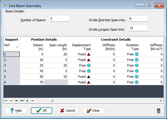
This form controls the input of the line beam geometry data.
Outline Procedure
Set the Navigation Pane Active Group to Structure Definition. This Line Beam Geometry form is shown when a new Line Beam model is defined (Add Model | Line Beam), or by selecting the Geometry tree node of an existing Line Beam.
Either:
- Enter the number of spans and edit the values in the table
- Press the + table button or the Insert key to insert a support. Note the support data is copied from the row above.
To reset the table to a single span use the Clear button.
To delete a row from the table, press the - table button or the Delete key to remove the selected row.
In the table enter either the distance from the left hand end to each support, or the length of each span in the appropriate column.
For analysis the span is divided into a series of beam elements along the span, and the number of elements can be controlled by entering the number of divisions in either the shortest span or the longest span. The number of divisions in all the other spans is set so that the lengths of each element are approximately the same in each span. The actual numbers of divisions in the individual spans is not particularly relevant to the results produced.
Sprung supports can be modeled by selecting the appropriate support constraints in the table, and entering the spring stiffness.
Note that 'drop-in' spans can be modeled by setting the displacement constraint to 'Free' at the ends of the drop-in span. Clearly this technique allows an upwards force in the drop-in span to be transferred to the rest of the structure, but this anomaly is not normally a problem in actual structures that need to be analyzed.
Form Graphic
Field Help
Number of Spans
Enter the number of spans of the continuous beam to be analyzed. A drop-in beam sitting on two cantilever beams is counted as 3 spans for this purpose.
Divide Shortest Span into
Divide Longest Span into
For analysis the span is divided into a series of beam elements along the span, and the number of elements can be controlled by entering the number of divisions in either of these fields. The number of divisions in all the other spans is set so that the lengths of all elements are approximately the same in each span. Data entered in either of these fields will cause the value for the other field to be recalculated and modified. The number in each span must be greater than 1 and not greater than 40.
Ref.
Display only - not editable.
Station
Enter the distance from the first support to the support defined by this row of the table. Alternatively the span length may be entered in the next column.
Span Length
Enter the span length of the span from the support defined by this row of the table to the next support. Alternatively the distance from the first support may be entered in the previous column.
Displacement Type
The support may be fixed to allow no vertical displacement or it may be assigned a spring stiffness such that displacement varies linearly according to the reaction at the support. Alternatively the support may be specified as 'Free' to displace vertically. In this case a hinged joint is inserted in the structural model. This technique may be used to model a drop-in span.
Stiffness (Displacement)
If 'Sprung' has been selected in the previous field, enter the reaction force to cause a unit displacement, using the currently defined units.
Rotation Type
The support may be fixed to allow no rotational movement or it may be assigned a spring stiffness such that rotation varies linearly according to the moment reaction at the support. Alternatively the support may be specified as 'Free' to rotate.
Stiffness (Rotation)
If 'Sprung' has been selected in the previous field, enter the reaction moment to cause a unit rotation, using the currently defined units.