
External Natural Convection
A device subject to external natural convection is immersed in the air or liquid. It heats up due to energy dissipation of its components, and convects heat to the surrounding air. As the air heats, the density varies, which leads to flow movement. This serves to convect more heat from the device.
Examples of external natural convection situations include a telecommunications device mounted to a wall, an electronics module sitting on a platform, or a light fixture suspended from a ceiling. Each of these scenarios requires a slightly different set-up.
The strategies presented cover most external flow natural convection situations. There may be variations based on the location of the device or obstructions, but these should provide guidance for such variations.
If these guidelines are followed, accuracy issues will usually be due to improper material property definitions or insufficient mesh. Additionally, there may be a significant amount of radiative heat transfer. To account for radiation effects, enable Radiation on the Solve dialog.
Device is Suspended in Free Air or in a Large Room
Modeling Considerations when suspended
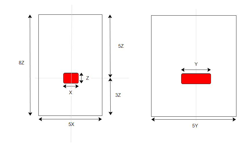
Construct a box that surrounds the device. This is the calculation domain, and is where the air flows around the exterior of the device. The box should be wide enough so that the flow is not artificially accelerated. (If the side walls are too close to the heated object, the flow may accelerate as in a nozzle). The top of the box should be farther away than the base to allow for eddie currents downstream of the object as the hot air rises. An approximate guideline for the size of this box is a height 8 times the vertical dimension of the device, and a width and depth that are 5 times the respective width and depth of the device.
Construct this either in the CAD system or with the External Volume Geometry tool.
Boundary Conditions when suspended
To define openings at the top and bottom, assign Static Gage Pressure = 0 to both surfaces
Bottom face (inlet): Static Temperature = ambient temperature
Apply a Total heat generation boundary condition to components that dissipate heat.
Device is Resting on a Platform or Table
Modeling Considerations when resting
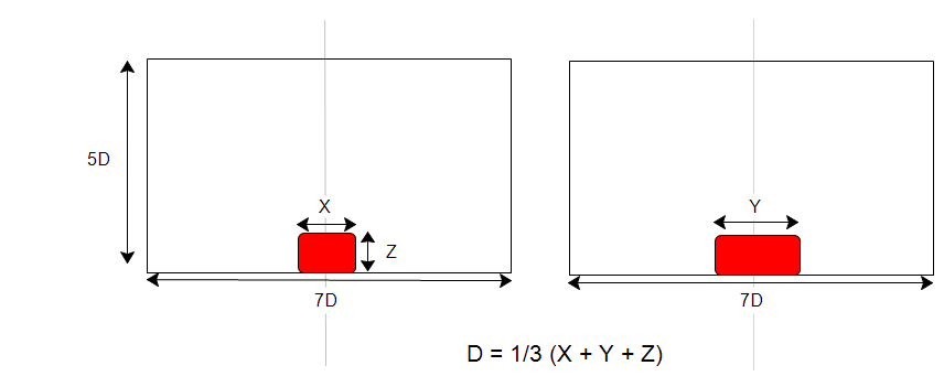
Construct a box that surrounds the device. This is the calculation domain, and is where the air flows around the exterior of the device. An approximate guideline for the size of this box is a height that is 5 times the average of the height, width, and depth dimensions of the device, and a width and depth that are 7 times this average of the device dimensions. This approach typically produces accurate flow and temperature distributions near the object if the domain is large enough, even if in reality air enters from all directions, in addition to the top.
Construct this either in the CAD system or with the External Volume Geometry tool.
Boundary Conditions when resting
- To define an opening (usually the top surface), assign Static Gage Pressure = 0.
- To assign a temperature constraint to the opening, specify a Film coefficient = 2 W/m²K and Reference Temperature = ambient temperature.
- Leave the bottom surface unspecified to simulate an insulated surface. The exception is if the bottom surface has a constant temperature or if heat is entering or leaving through the surface. Specify a temperature, a heat flux, or a film coefficient, respectively.
- Apply a Total heat generation boundary condition to components that dissipate heat.
Device is Suspended Near Ceiling
Modeling Considerations when hanging
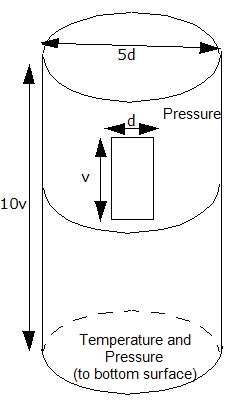
Construct a cylindrically shaped calculation domain that surrounds the device.
An approximate guideline for the cylinder height is 10 times the vertical dimension of the device. The diameter should be 5 times the width of the device.
The cylindrical surface should be divided vertically at approximately the same location of the device.
Boundary Conditions when hanging
Top: flat surface of cylinder, leave unspecified
Lower cylindrical surface:
- leave unspecified
- or optionally, specify a film coefficient (convection) boundary condition with ambient reference temperature.
Upper cylindrical surface
- specify gage pressure = 0
Bottom Surface of cylinder (flat surface)
- Specify ambient temperature and gage pressure = 0
Related Topics:
For more about natural convection modeling strategies...
Electronics Cooling Advanced Training
LED and Fluorescent Lighting Advanced Training
Example of External Natural Convection Analysis
Internal Flow Natural Convection Strategies