
Design Study Bar: Results Branch
You can use the Results branch and sub-branches to create, remove, and control the appearance of the results visualization entities. The commands in the right-click menus are also located in the on-model context menus and in the ribbon context menu for each entity type. The Design Study bar results branches collect these commands into a single area and are a convenient way to interact with the results tools.
Results Branch (top level)
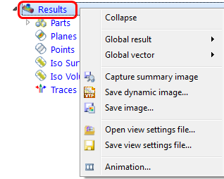
The right click menu provides a set of controls that apply to the entire model:
- Change the global result and global vector quantity.
- Capture an image to be used for comparing results in the Decision Center.
- Save a dynamic or static image of the currently results view.
- Open or save View Settings files.
- Open the Animation dialog for viewing a time- or iteration-history of your results.
Out of Date Results Warning Icon
If a setting is changed after a scenario is run, the warning icon appears on the Results branch:
This means that the results do not match the settings in the scenario. To resolve the inconsistency, run the scenario again with the new settings.
Parts Branch
Parts are organized by their assigned materials in the Parts branch. This is a convenient way to control the appearance and visibility of parts while reviewing results.
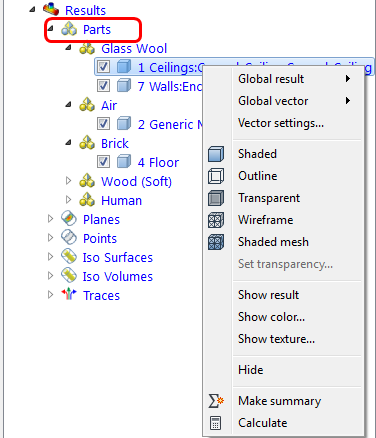
To hide a part, uncheck the box adjacent to the part ID.
These commands provide the ability to change the displayed result on a part, change part appearance, assign parts as Summary Parts, and to calculate part-based results such as temperature using the Parts tool.
Planes
From the Planes branch, you can create new results planes by right clicking on the branch, and clicking Add plane.
Every plane is listed as a sub-branch. To hide a plane, uncheck the box adjacent to the plane ID.
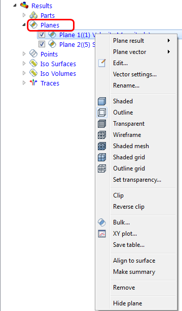
The right-click menu provides a comprehensive set of controls for Planes:
- Select the result and vector type
- Modify the appearance of the plane
- Enable clipping
- View Bulk results
- Create an XY Plot
- Align the surface to a location on the geometry
- Make a plane a Summary Plane for comparing results data
- Remove the plane
- Hide the plane
Points
From the Points branch, you can create new Results Points for monitoring time and iteration history of results at specific locations in the model.
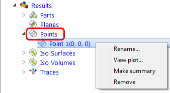
The right-click menu provides a comprehensive set of controls for Results Points:
- Change the name of a Point
- Plot the time- or iteration-history of results at the Point
- Make the Point a Summary Point to compare data from multiple scenarios at the same location
- Remove the point
Iso Surfaces
From the Iso Surfaces branch, you can create new Iso Surfaces by right clicking on the branch, and clicking Add iso surface.
Every Iso Surface is listed as a sub-branch. To hide an Iso Surface, uncheck the box adjacent to the Iso Surface ID.
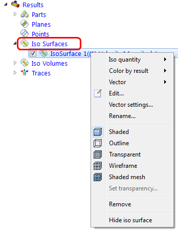
The right-click menu provides a comprehensive set of controls for Iso Surfaces:
- Select the Iso- and Color by result quantities
- Enable vectors and control vector settings
- Rename the Iso Surface
- Modify the appearance of the Iso Surface
- Remove the Iso Surface
- Hide the Iso Surface
Iso Volumes
From the Iso Volumes branch, you can create new Iso Volumes by right clicking on the branch, and clicking Add iso volume.
Every Iso Volume is listed as a sub-branch. To hide an Iso Volume, uncheck the box adjacent to the Iso Volume ID.
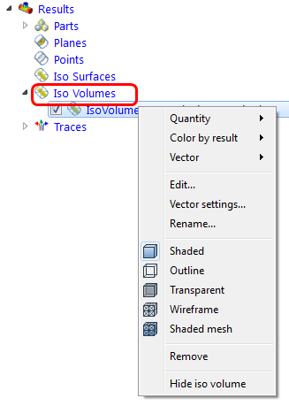
The right-click menu provides a comprehensive set of controls for Iso Volumes:
- Select the Iso- and Color by result quantities
- Enable vectors and control vector settings
- Rename the Iso Volume
- Modify the appearance of the Iso volume
- Remove the Iso Volume
- Hide the Iso Volume.
Traces
From the Traces branch, you can save trace data to an external file. To create new traces, use the Add command on the Traces context ribbon menu.
Every trace set is listed as a sub-branch. To hide a trace set, uncheck the box adjacent to the trace set ID.
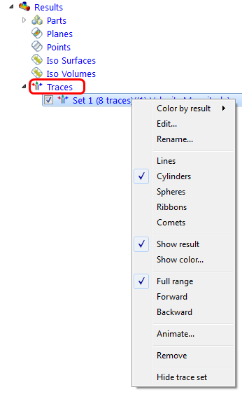
The right-click menu provides a comprehensive set of controls for particle traces:
- Select the displayed result quantity
- Open the Edit Trace Set dialog to edit the appearance
- Rename the trace set
- Change the appearance of the trace set
- Select between showing results or showing a uniform color
- Define the range of the traces
- Animate the trace
- Delete the trace set
- Hide the trace set
Viewing Suppressed Parts
Suppressed parts are excluded from the simulation. When results are displayed, suppressed parts appear shaded with a uniform color:
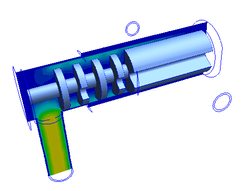
By default, suppressed parts are not visible when you first enter Results. To show them, open the Design Study bar, and expand the Parts branch of the Results branch. Check the box adjacent to each part you want to display.
There are some limitations for suppressed parts:
- Neither the mesh nor results can be displayed on suppressed parts.
- Individual surfaces of a suppressed part cannot be hidden.