Distributed Resistances
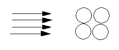
In some analyses, the actual flow geometry may contain a large number of holes or obstructions. For example, baffles are used in many electronics packages, and often have hundreds of holes through which the air must pass. To model each and every hole would be tedious, expensive and unnecessary.
The alternative is to simulate the presence of such holes or obstructions with a distributed resistance region. In this method, the mesh elements in this region are assigned a resistance parameter usually using either the free area ratio (proportion of free to total area) or a loss coefficient based on the known pressure drop. This resistance simulates the effect of the obstructions without using an inordinate number of elements. Other examples of porous media include radiators, vents, screens, filters and packed beds.
To Assign Resistances
Open the Material quick edit dialog. There are several methods:
- Left click on the part, and click the Edit icon on the context toolbar.
- Right click on the part, and click Edit...
- Right click on the part name under the Materials branch of the Design Study bar, and click Edit....
- Click Edit in the Materials context panel.
Select one or more parts.
Select the database from the Material DB Name menu.
Select Resistance from the Type menu.
Select the material from the Name menu.
Select the flow direction through the resistance using the pop-out dialogs. Select the two directions normal to the flow direction. See below for more details.
Click Apply.
Example showing assignment of a Distributed Resistance
Creating and Editing Distributed Resistance Materials
Notes
- You can assign the same distributed resistance material to multiple parts at the same time if the direction definitions (flow, normal 1, and normal 2) are the same for all of the selected parts. Each of the selected parts must have the same flow direction as well as the same two normal directions.
- Distributed resistance regions should not contact an external boundary condition.
- Boundary conditions should not be applied to any surface of a distributed resistance material. This may cause convergence difficulties and affects the flow rate value reported in the summary file.
- If a distributed resistance contacts an external boundary, it is good practice to add an extension onto the region so that the boundary condition is not applied directly to it.
Assignment Methods
There are three different way to assign the flow direction through a resistance region:
Aligned with a Cartesian direction
To align the flow through the resistance region with a Cartesian direction, open the pop-out dialog on the Flow Direction line, and select one of the Cartesian directions (Global X, Global Y, or Global Z). Select the remaining directions for the other two directions.
Not aligned with a Cartesian direction
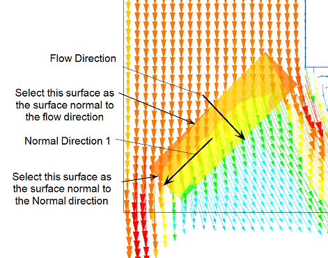
To align the flow with a selected surface, open the pop-out dialog, and click the Select Surface button.
Resistance values for the normal directions specified on the Resistance Material Editor will be used by the Solver. The following image shows flow passing through a resistance object that is inclined at an angle to the flow. In this example, the Flow and Normal Direction 1 resistances were set to the same value. Obviously, the values can be different if desired:
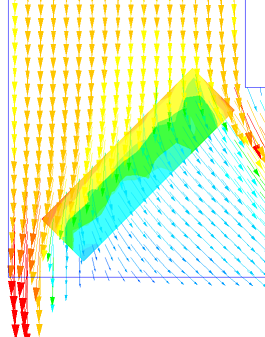
The flow is turned slightly, but is not completely realigned to be normal to the resistance object.
To force the flow to be normal to a resistance (to produce a “vent” resistance), set the Normal Direction resistances to be at least three orders of magnitude greater than the Through Flow K. This causes the flow to turn so that its direction is normal to the resistance object.
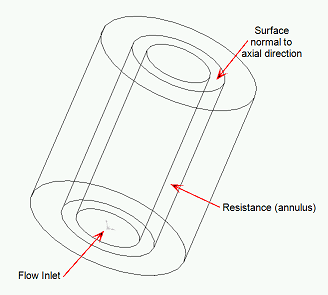
Through a Cylindrically Shaped Region
Use Radial for the Flow Direction to simulate a cylindrically-shaped resistance. The other two directions will automatically be set to Axial and Tangential.
Specify the direction of Normal Dir 1 to set the direction of this component. This is required for correct calculation of the orientation of the material object.
In Simulation CFD 2014, a new formulation was introduced for computing flow through cylindrically shaped regions. This method replaces a method that less accurately predicted pressure drop, particularly at low K values. This new method is enabled by default. To resort to the older method, change the value of the no_difu_tensors flag to 1 in the Flag Manager.
Another application for the Radial flow direction resistance is for a bank of resistive cylinders over which the flow must pass. In this case, the flow direction is again Radial, and an axial direction (select a surface normal to the axis of the cylinder) must be selected: