Trim a surface by removing (actually hiding) any part of the surface bounded by curves-on-surface or cross sections. This lets you create complex edges and holes in NURBS surfaces. You can also split (divide) a surface into multiple surfaces.
You can create the bounding curves-on-surface while inside the Trim Surface tool, by projecting curves on the surfaces(s) or you can automatically create a trimming curve-on-surface from the intersection of a surface with the target surface(s).
You can also create curves-on-surface before using the Trim Surface tool.
Cross sections are created using Windows > Editors > Cross Section Editor.
See the following sections for more information:
- Create curves-on-surface offset from a curve
- Create curves-on-surface where a surface intersects other surfaces or a plane
- Create curves-on-surface by projecting curves onto surfaces
- Troubleshooting trimmed surfaces
- Create or view cross sections
You can trim more than one surface at a time, using one or more projected curves or intersecting surfaces.
Trim or divide a surface by projecting curves on surfaces
- Choose Surface Edit > Trim > Trim Surface

 .
. - In the control window, turn on 3D Trimming and choose Normal under Vector Options.
- Select all the surfaces you want to trim. Hold down the
 key to pick more than one surface, or use a pick box.
 - Select the curves you want to project onto the surface to create trim curves (curves-on-surface). If the desired curves-on-surface are already present, you can skip this step.
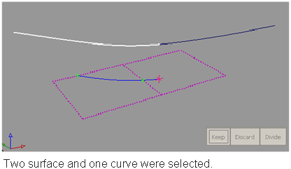 Note:
Note:The surfaces and curves can be selected in any order, but the first object selected must be a surface.
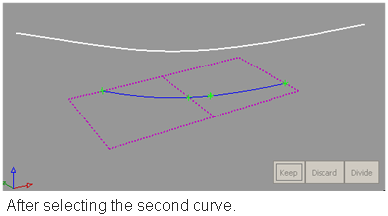
As you select surfaces and curves, the curves are automatically projected onto the surfaces, and the corresponding trim curves are displayed on the surfaces.
Note:By default, the direction of projection is determined by the view vector of the window where you selected the curves ( that is, perpendicular to the window). To project normal to the surface, you must select the Normal option.
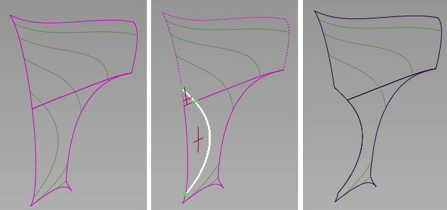
- Click on the regions of the surfaces that you either want to keep or discard. (Regions are areas delimited by curves-on-surface). If the trim regions are spread across multiple surfaces, you can box-select them.
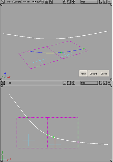
Crosshairs appear on the selected regions. To move a crosshair, click it and drag.
If those region selectors appear too large or too small on your geometry, you can adjust their size by using the Region Selector U Size and V Size sliders in the control window.
Tip:You do not have to click a “visible” part of the surface (such as an isoparametric curve). Clicking anywhere inside the surface edges will also work.
- At any time, before performing the next step, you can change the vector option in the control window to change the direction of projection.
The curves-on-surface update.
Note:If you choose Picked, you must then pick a vector object along which to project. (See Create or edit a reference vector.)
Note:If you choose View, you can project different curves along different view vectors. However, if you then click Refresh View Vector, or select a different vector option, all curves-on-surface update to match the current projection vector.
- Click one of the buttons: Keep, Discard, or Divide, depending on the type of operation you want to perform.
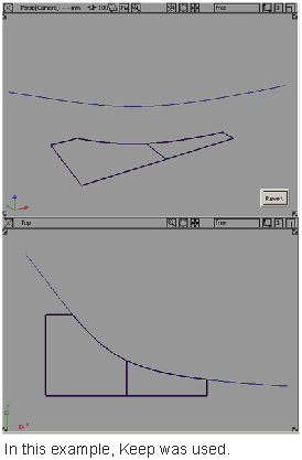
Keep: Keeps the regions selected in step 5, and discards the rest.
Discard: Discards the regions selected in step 5, and keeps the rest.
Divide: Divides the selected regions from the others (making separate trim surfaces) but keeps all the regions.
- After the trim operation has been performed, you can undo it by clicking the Revert button.
You are left within the tool with all your selections intact, so you can adjust your selections and trim again.
Note:A successful trim curve is shown with a green marker where the ends of the curve join.
 Note:
Note:An unsuccessful trim curve — as in this case, where a gap exists — has the two ends of the curve highlighted in yellow to call attention to the gap region.
Trim or divide a surface along the intersection of another surface
- Choose Surface Edit > Trim > Trim Surface .
- In the control window, select 3D Trimming and choose Intersect as the method.
- Select all the surfaces you want to trim. Hold down the key to pick more than one surface, or use a pick box.
- Select the intersecting surfaces you want to use to create the trim curves (curves-on-surface).
As you select surfaces and intersecting surfaces, the trim curves are automatically created and displayed on the surfaces.
Note: If you box-select several surfaces, and some of them are already selected for trimming, Alias picks the unselected surfaces and intersects them with the selected surfaces. - Click on the regions of the surfaces that you either want to keep or discard. (Regions are areas delimited by curves-on-surface). If the trim regions are spread across multiple surfaces, you can box-select them.
Crosshairs appear on the selected regions. To move a crosshair, click it and drag.
If those region selectors appear too large or too small on your geometry, you can adjust their size by using the Region Selector U Size and V Size sliders in the control window.
Tip:You do not have to click a “visible” part of the surface (such as an isoparametric curve). Clicking anywhere inside the surface edges will also work.
- Click one of the buttons: Keep, Discard, or Divide, depending on the type of operation you want to perform.
Keep: Keeps the regions selected in step 5, and discards the rest.
Discard: Discards the regions selected in step 5, and keeps the rest.
Divide: Divides the selected regions from the others (making separate trim surfaces) but keeps all the regions.
- After the trim operation has been performed, you can undo it by clicking the Revert button.
You are left within the tool with all your selections intact, so you can adjust your selections and trim again.
Note:A successful trim curve is shown with a green marker where the ends of the curve join.
Note:An unsuccessful trim curve — as in this case, where a gap exists — has the two ends of the curve highlighted in red to call attention to the gap region.
Trim or divide a surface using cross sections
- Choose Surface Edit > Trim > Trim Surface .
- In the control window, check on 3D Trimming.
- If you are trimming a surface with its own cross-sections, choose Normal under Vector Options.
- Select the surface to trim (hold down the key to add more surfaces to the selection).
- Select the cross sections to use as trimming curves.
- Click on the regions to keep or discard.
- Click the Keep, Discard, or Divide button.
Trimming both a regular surface and a trimmed surface with their Y-sections.
What if...?
I can’t trim a surface because the curves-on-surface are outside tolerance?
To change the tolerances governing trim operations, choose Preferences > Construction Options![]() and open the Curves On Surface/Trim section.
and open the Curves On Surface/Trim section.
Trim Curve Fit controls the accuracy of the trim boundaries created using the trim tool.
Max Gap Between Curves is the maximum gap allowed between the endpoints of two curves-on-surface (or a curve-on-surface and a surface edge) to consider them closed when defining a trim region.
A successful trim curve is shown with a green marker where the ends of the curve join.
An unsuccessful trim curve — as in this case, where a gap exists — has the two ends of the curve highlighted in yellow to call attention to the gap region.