There are four Control Buttons. Start by creating only one, and then later duplicate it to create the other three.
Each button is symmetrical, so to save time, build one half of one button, and use mirroring to create the other half.
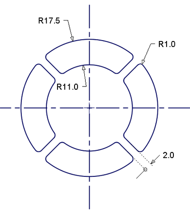
The following image shows the dimensions for the buttons.
Create the button surfaces using the Revolve, and Round tools.
Open the tutorial file (optional)
If you successfully completed part 5, proceed to the next step, Create control button revolved surface.
If you were not successful in part 5, open the file called MP3Player_Part5.wire, located in the wire folder of the CourseWare project. This file contains the completed model from part 5.
Create control button revolved surface
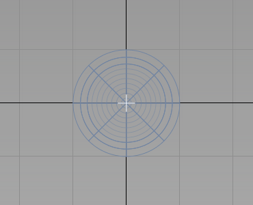
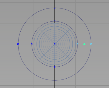
First create the outline circles for the button design.
- Maximize the Top window
- Choose Layers > New
 to create a layer. Change the name of the layer to Control Buttons.
- Choose Curves > Keypoint Curve Toolbox
 , then Keypoint Curve Tools > Circular Arc
 . You are prompted to enter the center of the circle.
 Type in 0 to place the center of the circle at the origin.
You are prompted to enter a point on the radius of the circle.
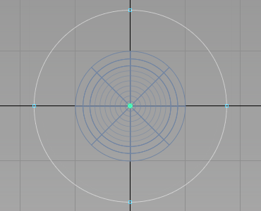
Type 17.5 to create a circle with a radius of 17.5 mm.
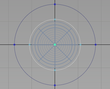
- Choose Curves > Keypoint Curve Toolbox, then Keypoint Curve Tools > Circular Arc again, and create a circle with the center at the origin and a radius of 11 mm.
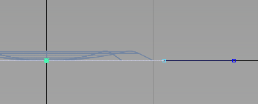
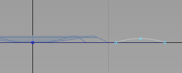
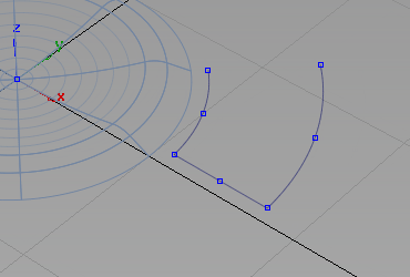
Now use these circles to create an arc for the top surface of the buttons.
Maximize the Left window and zoom into the right-hand side of the circles. Use the Keypoints on the two circles to locate the arc.
- Choose Curves > Keypoint Curve Toolbox, then Keypoint Curve Tools > Arcs > Arc (three point)
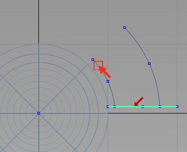
 . You are prompted to place the start point of the arc. Use point snap (
 (Windows) or
  (Mac) key) and select the keypoint on the inner circle.
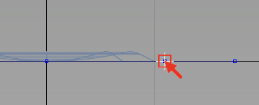
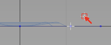
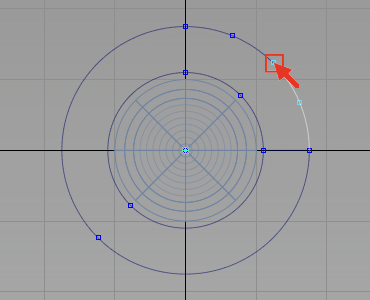
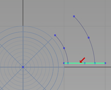
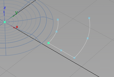
When prompted for the next point on the arc, select an approximate location for the peak of the curve. The location does not need to be accurate, as later you set the radius of the arc accurately using the Information window.
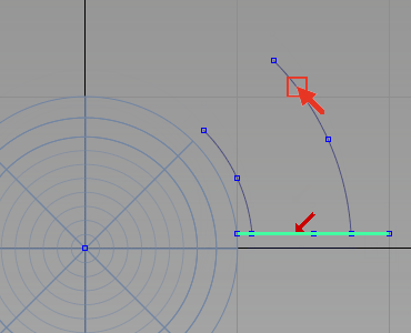
When prompted to place the end point of the arc, use the point snap (
(Windows) or (Mac) key) again and choose the keypoint on the large circle. 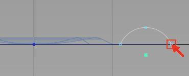
The arc is created at an approximate radius, but with an accurate start and end point.
- With the arc still selected, choose Windows > Information > Information Window
 .
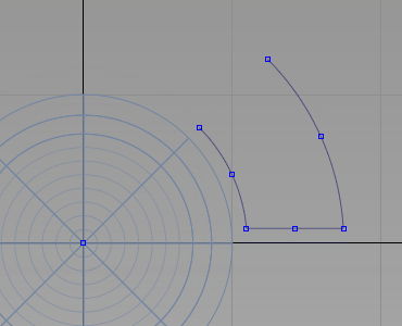
. Open the Attributes section, and change the Arc Length/Radius to 10.
The radius is changed, but the end points remain in the same locations.
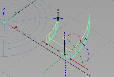
Now move the arc up to raise the button surface above the casing.
- With the arc still selected, choose Transform > Move
 and type r0,0,0.75 to move the arc up 0.75mm in the z-direction.
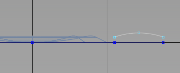
- Maximize the Top window. Leave the curve selected. Use it to create a revolved surface.
- Choose Surfaces > Revolve
 and double-click the icon to open the option window.
 Change the Sweep Angle to 45, the Segments to 4, and ensure that Axes is set to Global and the axis set to Z.
Turn off Continuity Check if it is on. Click Next.
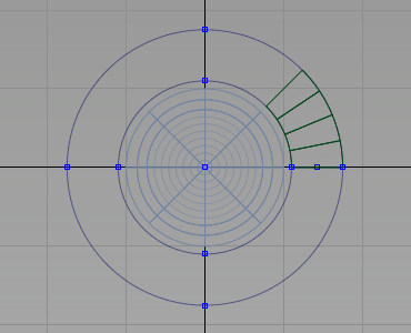
The revolved surface is created.
Now temporarily hide the revolved surface and the arc, to make it easier to work on the outline curves.
- Choose Pick > Object
 and select the surface and the arc.
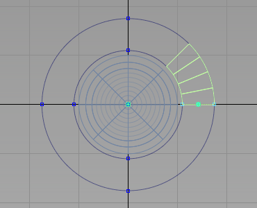
- Choose ObjectDisplay > Invisible
 to hide the surface and the curves temporarily.
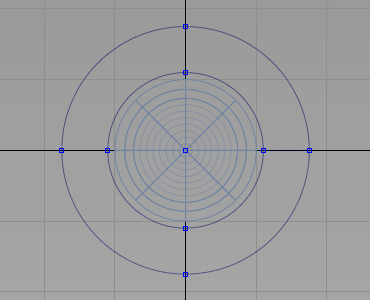
Create the control button draft surfaces
Now trim the two circles to create the button outline.
- Choose Curves > Keypoint Curve Toolbox, then Keypoint Curve Tools > Break & Join > Break Curve at Keypoint
 .
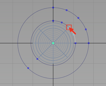
. Click the top keypoint of the outer curve.
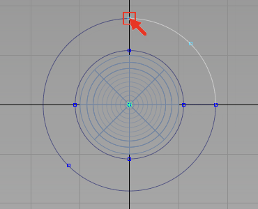
Still in the Break at Keypoint tool, click the top keypoint of the inner curve.
The curve is split, and the top right-hand segments now have keypoints at their centers.
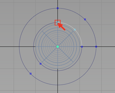
Now break the curves at these keypoints to create a 45 degree segment.
Click the middle keypoint of each curve to break it into 45 degree segments.
- Choose Pick > Object and select the parts of the circles you do not need.
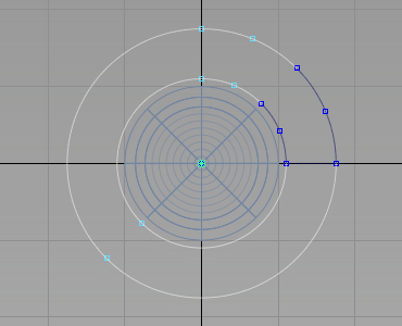
- Press the
 key to delete the curves.
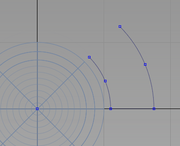
Trim Curves
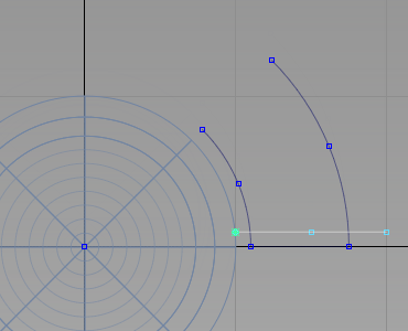
Next trim the two arcs and the line to create the outline of a single button.
- Choose Curves > Keypoint Curve Toolbox, then Keypoint Curve Tools > Lines > Line
 and snap to the grid points (
 (Windows) or
  (Mac) key) to create a horizontal line. Create the line over-long so that you can use it for trimming.
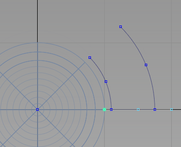
- Choose Transform > Move and type 0,1 to move the line up by 1 mm in the y-axis.
- Choose Curve Edit > Curve Section
 .
. You are prompted to select a curve to trim. Click both arcs, above the line and click the Go button
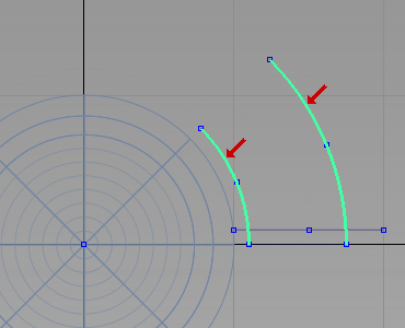
You are prompted to select the trimming curves. Choose the line.
The arcs are trimmed.
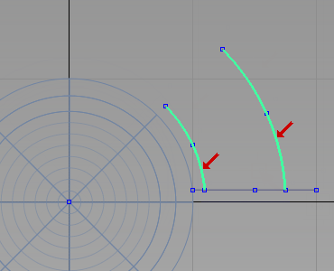
- Choose Curve Edit > Curve Section again and this time choose the line. Make sure that you select the curve between the arcs, to keep that part of the line, and click Go.
When prompted to select the trimming curves, first choose the outer arc.
Then choose the inner arc to complete the trimming.
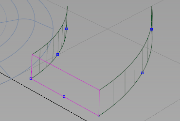
Create the draft surfaces
- Maximize the Perspective window.
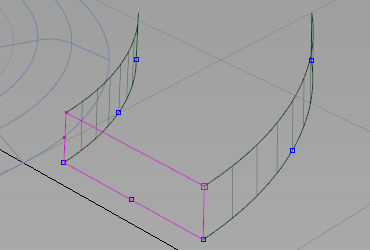
- Choose Pick > Object and select two curves as shown.
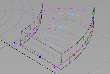
- Choose Surfaces > Multi-Surface Draft
 and double-click to open the option window.
 Modify the settings to Draft Angle -2 degrees, a Length of 2 mm, select Intersect Flanges, and click Build.
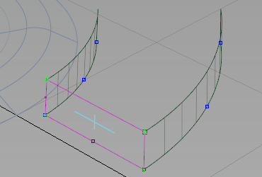
Tip:The pull direction may be set to –z from the last Draft operation. Click the dotted blue line to make sure that the blue arrow is pointing upwards in a positive z direction.
 Note:
Note:Depending on your curves, you may need to change the Draft Angle to +2 to get the side walls falling inwards with the draft.
- Choose Delete > Delete Construction History
 .
.
Intersect and trim the buttons
Now intersect and trim the button surfaces to create a trimmed model and then use the Round tool to complete the button design.
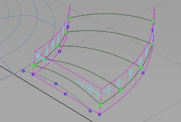
- Choose Surface Edit > Create CurvesOnSurface > Intersect
 .
. - Select the middle draft surface and click Go.
- Click the adjacent draft surfaces. Intersecting curves are created.
- Choose Surface Edit > Trim > Trim Surface
 .
. - Click the middle draft surface, then click it again to select it for trimming.
- Click Keep. The surface is trimmed.
- Repeat for the other two surfaces.
- Choose ObjectDisplay > Visible
 to make the revolved surface of the button visible again.
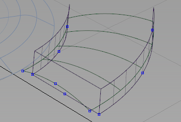
- Choose Pick > Object and pick the draft surfaces.

- Choose Surface Edit > Create CurvesOnSurface > Intersect.
As the draft surfaces have already been selected, you are prompted to select the intersecting surfaces.
Select each segment of the control button to select the intersection surfaces.
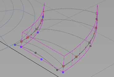
The surfaces are intersected and curves-on-surface created.
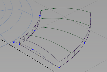
- Choose Surface Edit > Trim > Trim Surface.
Follow the prompts to trim the revolved surface.
Trim the top parts of the draft surfaces.
- Choose Pick > Component
 to select all the curves and Assign them to the Curves layer.
 - Select all the surfaces and choose Delete > Delete Construction History .
Round Multiple Edges
- Choose Surfaces > Round
 and double-click the option box to open the option window.
 - Expand Default Corner Types and change the Unequal Radius Corner to Single Surface to create a simple rounded corner.
- Select one of the side edges, and enter 1 on the prompt line to set the round radius to 1 mm.
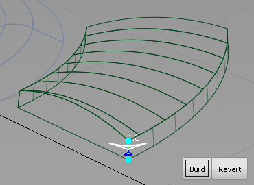
- Select the other side edge and leave the radius value at 1.
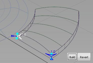
- Select one of the top edges and type in 0.35 in the prompt line to change the round radius to 0.35mm.
- Select the other top edges.
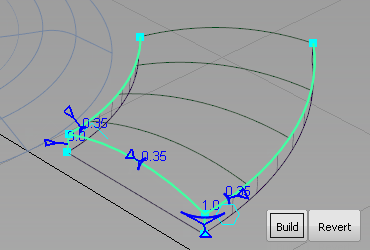
- Click the Build button to create the round.
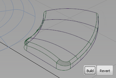
The advantage of using the round tool on multiple edges is that the blended corner surfaces are built automatically.
Save your work
Save your work in the wire folder of the Lessons project. Name your file myMP3Player6.wire.