In this part of the tutorial, create part of the cable that connects the joystick to the computer.
Open the tutorial file (optional)
If you successfully completed part 3, you can proceed directly to the next step, Create the cable path curve.
If you were not successful in part 3, open the file called joystick_Part3.wire, located in the wire folder of the CourseWare project. This file contains the completed model from part 3.
Create the cable path curve
- Maximize the Top view. Choose Layouts > Top
 or F5.
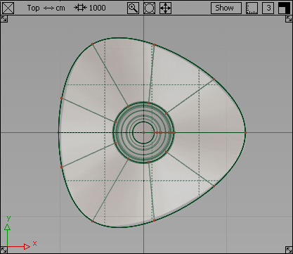
You are creating the cable on the left of the joystick, so modify the view to give you more space.
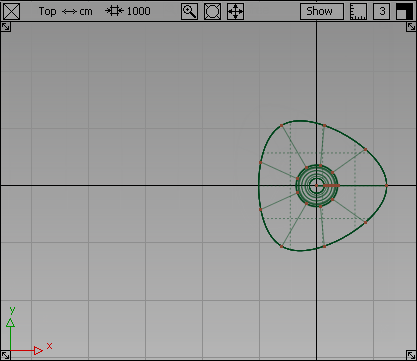
- Zoom out of the view by holding down the
 and
and  (Windows) or and
  (Mac) keys and use the
  . With the and (Windows) or and (Mac) keys still held down, pan the view using the
  so there is some free space to the left of the joystick.
 You no longer need the reference sketches, so hide the canvas plane by choosing WindowDisplay > Toggles > Canvas Planes
 .
. 
- Choose Curves > New Curves > New CV Curve
 .
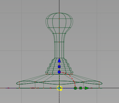
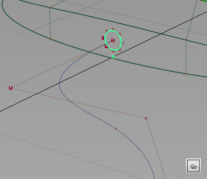
. - Turn on grid snapping by holding down the (Windows) or (Mac) key, and click the grid intersection at the left side of the base.
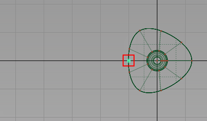
The first CV of the curve is created.
- Now create the second CV.
Click and drag with the
to position the second CV to the left of the first. Release the . 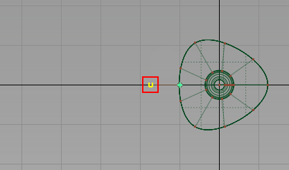
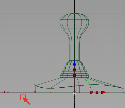
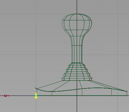
- Continue to place CVs, creating a wavy path for the cable.
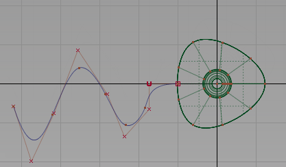
Create the cable profile curve
Next, create a small circle for the cross-section profile of the cable.
- Maximize the Back view. Choose Layouts > Back
 or F7.
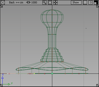
- Choose Curves > Primitives > Circle
 .
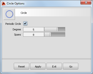
. - Double-click the icon. The Circle options box opens.
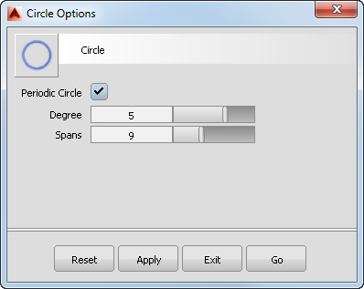
The current options have 9 spans which you set previously for the triangular shape. A good general-purpose circular shape has eight sections, so change the number of spans to 8 and click Go.
- Turn on grid snapping by holding down the (Windows) or (Mac) key. Click near the origin in the Back window to place the circle at the center of the base.
A small circle is placed at the origin. The CVs are highlighted in yellow and the manipulator is showing.
- Switch to the Left view. Choose Layouts > Left
 or F6.
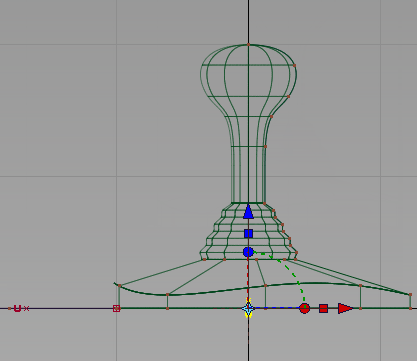
The circle is at the origin. Next, move the circle to the left edge of the joystick base, where the path curve begins.
- With the circle still selected, choose Transform > Move
 .
. - Turn on grid snapping by holding down the (Windows) or (Mac) key. Click near the grid point where the path curve starts, being careful not to select any other geometry.
The circle moves to the start of the path.
Now move the circle and the start of the path curve upwards, so the cable emerges from the middle of the base side wall.
-
Choose Pick > Nothing
 to deselect the circle.
 - Choose Pick > Point Types > CV
 and drag a box around the circle CVs and the first two CVs on the path curve.
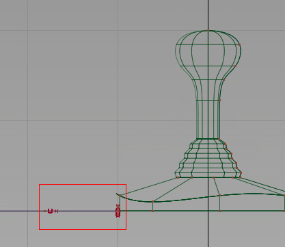
- Choose Transform > Move.
- Drag with the to move the selected CVs upwards, so the circle sits in the middle of the sidewall of the base.
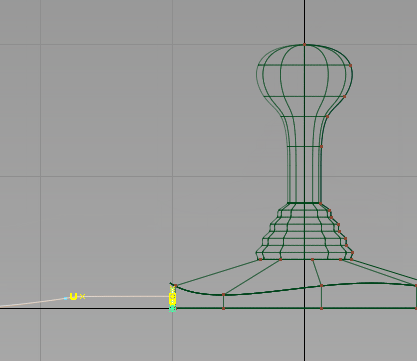
- Choose Pick > Nothing to deselect the CVs.
- Switch to the perspective view. Choose Layouts > Perspective
 or the F8 hotkey.
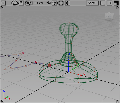
The small circle is at the start of the path curve, centered on the side wall of the base.
Create the cable surface
Next, create the extruded surface for the cable.
- Tumble the perspective view and zoom in to the area at the start of the cable. Hold down the and (Windows) or and (Mac) keys and use the
 to tumble the view, and the to zoom in.
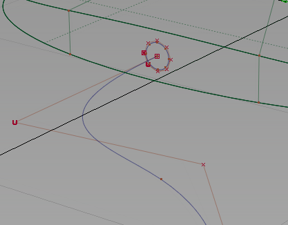
To create the cable surface, extrude the small circle along the path curve.
- Choose the Surfaces > Swept Surfaces > Extrude
 tool.
tool. - You are prompted to select the curves to extrude. Click the circle.
Click the Go button to choose the circle as the generation curve.
- You are prompted to select the extrude path. Click the long wavy curve.
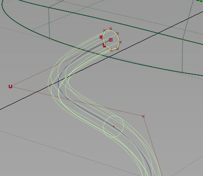
The extruded surface is created.
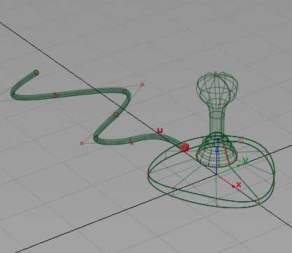
- Choose Pick > Nothing to deselect the surface.
- Tumble and zoom out to view the cable surface.
Save your work
- Choose File > Save As
 to save the current scene.
 - Save your work in the wire folder of the Lessons project.
- Name your file myjoystick4.wire.