Shades the picked surfaces with a color map showing areas in and out of draft, for checking mold manufacturability.
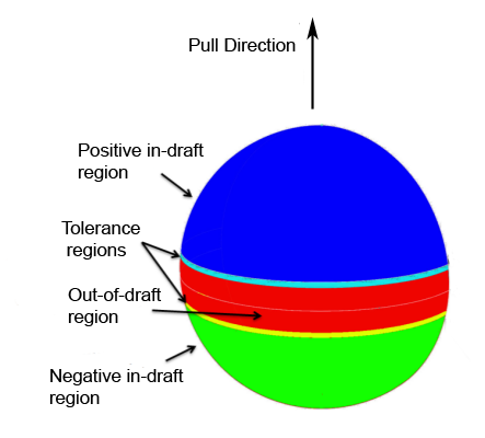
This shading mode shows you which parts of a surface are in-draft and out-of-draft for both directions of a specified pull vector (since a mold often separates in both directions) and for positive/negative draft angles. Positive and negative in-draft and out-of-draft regions of the surface, as well as tolerance regions, are shaded different colors. Tolerance regions are "grain wash" zones that form part of the out-of-draft regions.
You can generate the draft angle shading by using either diagnostic shading, or, for more options, the Evaluate > Parting Line tool.
Using the Draft Angle diagnostic shading
- Click the
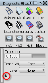
 button in the Diagnostic Shade window.
- Click the small triangle (as shown below) to display the shading options.
- In the Type pop-up menu, choose Draft Angle.
- Choose whether to specify the pull direction as a rotation (from the normal “up” direction) or as a vector, then enter the X, Y, and Z values. Note:
If you want to use an existing vector or plane to specify the pull vector, pick it, then click the Update From Selection button. This automatically sets the X, Y, Z coordinates to the correct values in the window.
- Check or uncheck the Positive Draft and Negative Draft check boxes depending on whether you want to see the draft angle data along one or both directions of the pull vector.
- Do any of the following:
- Set the positive and/or negative draft angle(s).
- Set the positive and/or negative tolerance angle(s) to show the tolerance region(s) between in-draft and out-of-draft regions.
- Adjust the transparency of the shader.
The shading updates on your objects. You may see up to five colors, as shown bellow.
What if...?
- I don’t know what vector values I need?
-
- Use the Construction > Vector
 tool to create a reference vector, and point it in the direction you want.
 - Pick the reference vector and click the Update From Selection button under the Draft Angle options in the Control Panel. (If you pick a plane instead, the direction perpendicular to the plane is used.)
The X, Y, and Z coordinates of the vector are automatically set.
- Use the Construction > Vector
- I don’t know what pull direction, draft angle, in-draft, out-of-draft, mean?
-
Some manufacturing processes, like injection molding, need you to design molds. When a mold is used it is pulled away from the finished part along a pull direction, and sometimes in two opposite directions simultaneously .
Angle-to-pull is the angle between the surface tangent plane at a surface point and the pull vector. When the angle-to-pull is 0 degrees, the pull vector is parallel to the surface tangent plane at that point. When the angle-to-pull is 90 degrees, the pull vector is normal to the surface.
Most manufacturing processes require that the angle-to-pull for a molded surface be greater than some angle, for example 1 degree, or else the molded part will not separate from the mold. This angle is the draft angle.
When the angle-to-pull is less than the draft angle, the surface point is out-of-draft. When the angle-to-pull is more than the draft angle, the surface point is in-draft.
Using the Parting Line tool
The Evaluate > Parting Line![]() tool in the Palette lets you create curves-on-surface (or just visual curves) along the draft lines and parting line, in addition to draft angle shading.
tool in the Palette lets you create curves-on-surface (or just visual curves) along the draft lines and parting line, in addition to draft angle shading.
The tool also provides a manipulator and standard vector options in the control window to help specify the pull direction.
See Create curves on surface from evaluation data for more information.