In this section, create the dust bag and cable connector surfaces at the rear of the vacuum cleaner.
Open the tutorial file (optional)
If you successfully completed part 6, you can proceed directly to the next step, Extract the body shape.
If you were not successful in part 6, open the file called vacuum_Part6.wire, located in the wire folder of the CourseWare project. This file contains the completed model from part 6.
Extract the body shape
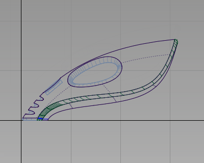
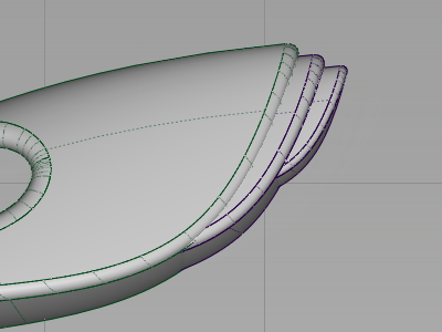
At the back end of the vacuum cleaner there are two more components, a dust bag and a cable connector, shown in the following image.
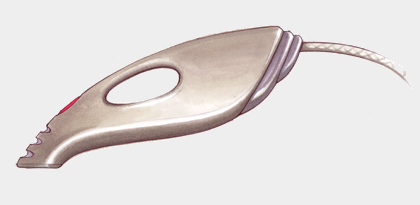
Create these components as scaled copies of the rear surfaces of the main vacuum cleaner body. By using the same shape, you create a rhythm of similar shapes, which gives the design its character.
Start by creating copies of the body surfaces and placing them onto a new layer.
- Choose Layouts > Left
 to maximize the Left window.
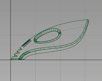
- Choose Layers > New
 to create a layer.
 - In the Layer Bar, rename the new layer dustbag.

Now make a copy of the surfaces and assign them to the dustbag layer.
- Choose Pick > Object
 and drag a pick box around the end surfaces of the vacuum body. Make sure that you do not select the handle or handle fillet surfaces.
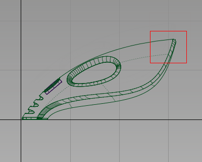
- Choose Edit > Copy
 followed by Edit > Paste
 . A copy of the surfaces is made, placed on top of the originals, and highlighted.
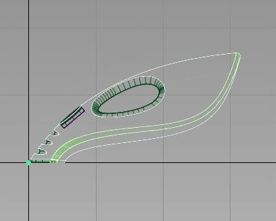
- In the Layer Bar, click and hold on the dustbag layer to see the drop-down menu. Choose Assign to assign the copied surfaces to the dustbag layer.
- Choose Pick > Nothing
 to deselect the surfaces.
 - On the Layer Bar, click and hold on the body layer and choose Set state > Inactive to make the body surfaces inactive.
The layer tab is displayed in blue to indicate that it is inactive.

- Do the same for the power_button layer to make the power button surfaces inactive.
Now, only the copied surfaces on the dustbag layer are displayed and pickable.
Trim the dust bag surfaces
Only the ends of the body surfaces are required for the dust bag and cable connector.
Next trim the surfaces so only the rear part of the shape is left, to make the surfaces easier to work with and easier to visualize.
Trim the surfaces by using a curve to define the cutting line.
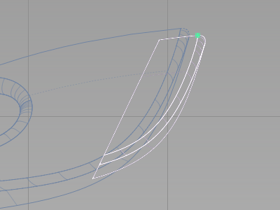
- Choose Curves > New Curves > New Edit Point Curve
 .
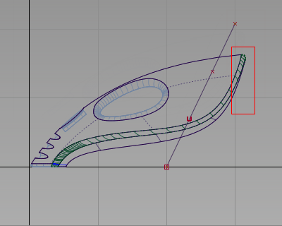
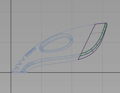
. You are prompted to enter the new edit point position. Hold down the
 (Windows) or
  (Mac) key and click near the grid intersection shown in the following image to position the first edit point of the curve.
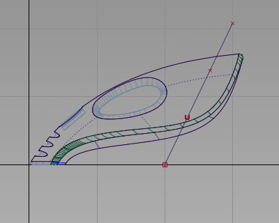
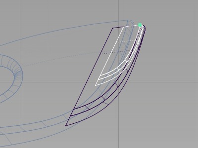
Place the second edit point by clicking and holding the
 . Keep the mouse button held down and move the edit point until the curve is roughly at the same angle as the back of the vacuum.
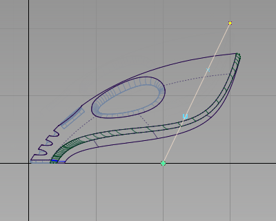
Make sure that your curve is long enough to extend beyond the body surfaces.
- Choose Pick > Nothing to deselect the curve.
The Trim tool can be used to create a curve-on-surface directly from a projected curve before trimming the surface. Now use the curve you have drawn to cut away the front end of the surfaces.
- Choose Surface Edit > Trim > Trim Surface
 and double-click the icon to open the option box. Click the 3D Trimming checkbox to turn on the projection option in the trim tool.
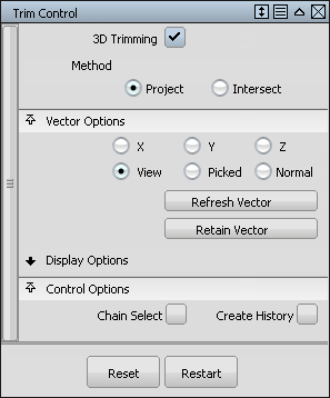
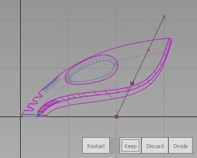
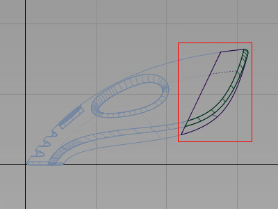
- You are prompted to select the surfaces to trim. Click and drag a pick box around all the surfaces.
The surfaces are selected and highlighted in pink.
You are then prompted to select one of the following:
Shift select to add or remove surfaces or select trimming curves or click or box select trim regions.
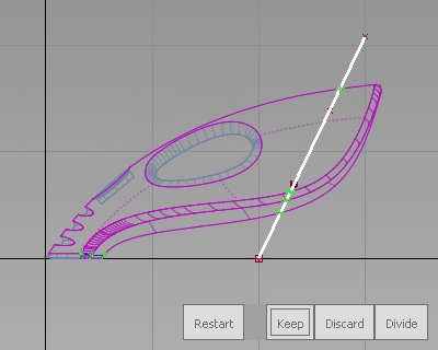
This time, use the Trim tool to project the curve onto the surfaces, and so respond to the second prompt.
- Click the curve you just created to select it as a curve to project.
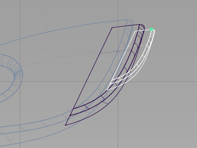
- To see the effect of the projection, press the F8 hotkey to switch to the perspective view.
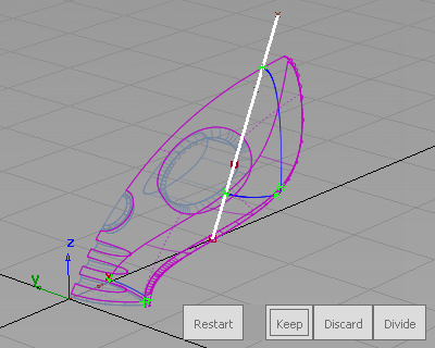
You can see that a curve-on-surface has been created across the surfaces and is shown in bright blue.
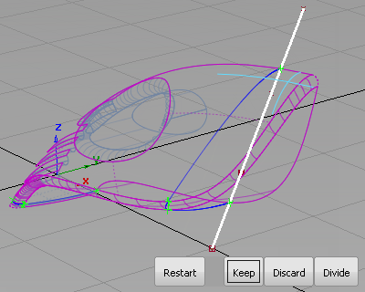
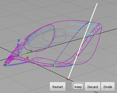
Still in the trim tool, you are now prompted with the three options. This time you want to select a region of each surface to keep.
- Zoom and tumble the view to get a close-up view of the rear of the vacuum.
- Click in the rear part of the upper surface to select it as the part to keep.
An indicator appears on the surface to show that it is selected for trimming.
- Click the rear part of the fillet. Avoid clicking any of the lines on the fillet surface, so that they are not mistaken for projection lines. Tip:
Zoom in to make it easier to select a part of the fillet surface with no lines.
An indicator appears on the surface to show that it is selected for trimming.
- Click the rear part of the lower surface.

An indicator appears on the surface to show that it is selected for trimming.
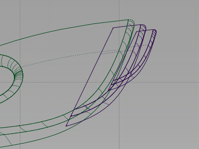
- Click Keep in the bottom right corner of the view to keep the ends of the surfaces.
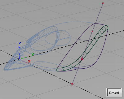
The surfaces are trimmed.
- Choose Pick > Object and select the curve.
-
Choose Delete > Delete Active
 , or press the
  key on the keyboard to delete the curve.
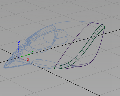
You have trimmed out a part of the vacuum design that can now be used to create the dust bag and cable connector.
Note:The original body surfaces are unchanged, and are shown on the invisible (pale blue) layer.
Scale the dust bag and connector
Next group the surfaces so that they can be scaled and positioned to complete the design of the dustbag.
- Choose Layouts > Left to switch to the Left view.
- Choose Pick > Object and drag a pick box around all the surfaces.
- Choose Edit > Group
 . The surfaces are now grouped with a single pivot point, placed at the origin.
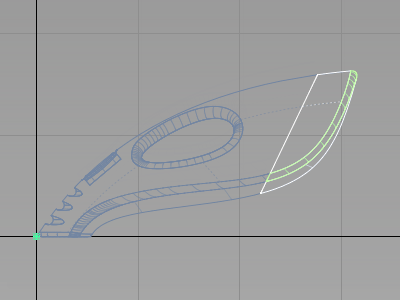
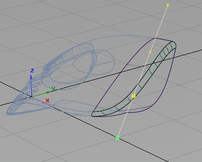
Next move the pivot point to the end of the surfaces using curve snapping. Use the pivot point to control the scaling of the surfaces.
- With the group still selected, choose Transform > Local > Set Pivot
 . Hold down the
  and (Windows) or
  and (Mac) keys to turn on curve snapping. Point the cursor exactly on the top edge of the upper surface. (Zoom in to view the area in more detail.)
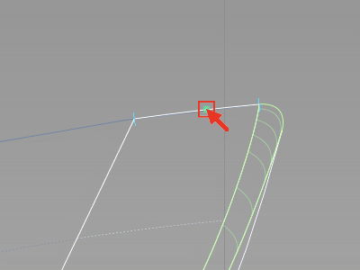
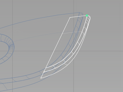
Drag with the
to the pale blue cross at the right end of the surface to position the pivot point at the end of the surface edge. 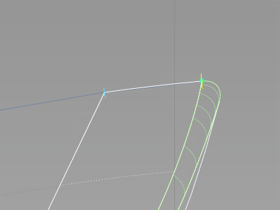
- Choose Transform > Scale
 and type a value of 0.85 and press
  (Windows) or
  (Mac) to shrink the surfaces. A dialog box appears asking whether you want to delete the construction history for the surfaces. Click Yes.
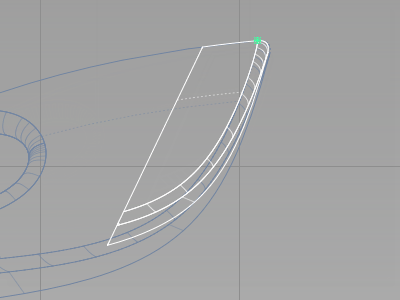
The surfaces are scaled smaller to form the dustbag.
- Choose Transform > Move
 . You are prompted to enter the move amounts.
The prompt line displays (ABS) to indicate absolute mode. In absolute mode, coordinates that are typed are measured from the origin.
Since you are moving the dustbag only slightly from its current position, switch to relative dimensioning, so the coordinate values move the surfaces relative to their current position.
- Type r and press (Windows) or (Mac).

- Type 125,0,-50 and press (Windows) or (Mac) to move the dust bag 125 mm in x and -50 mm in z.
 Note:
Note:You can type the x,y,z values with either a space or a comma separating the numbers.
The dustbag is now in position.
Create the cable connector
The cable connector component is created in the same way.
- With the dustbag still selected, choose Edit > Copy followed by Edit > Paste.
A copy of the dustbag is created and is selected, ready to transform.
- Choose Transform > Scale. Type 0.6 and press (Windows) or (Mac) to reduce the size of the group of surfaces.
- Choose Transform > Move. Type 125, 0, -50 and press (Windows) or (Mac) to move the cable connector 125 mm in x and -50 mm in z.
 Note:
Note:If you want to adjust the design, move the surfaces freely using the mouse buttons.
- Choose Pick > Nothing to deselect the surfaces.

- On the Layer Bar, click and hold on the body layer to see the drop-down menu. Choose Set state > Pickable to view the main body. Do the same for the power_button layer.
- Use Diagnostic Shade to view the completed dustbag design.
For a concept design, it is typical to make changes regularly to the model. During this phase, it is acceptable to leave the dust bag and connector surfaces overlapping with the main body shape. Leaving the surfaces overlapping allows you to quickly experiment with scaling and moving the components to explore the design.
When the design is resolved, you would trim away the parts of the surfaces that are intersecting the body, to create a continuous outer surface. This trimming is covered in Part 8, an optional extra stage in this tutorial.
Save your work
- Choose File > Save As
 to save the current scene.
 - Save your work in the wire folder of the Lessons project.
- Name your file myvacuum7.wire.