In this section, create the on/off button for the vacuum cleaner.
Create the button detail in two stages. First, create a recess in the body surface where the button sits. Then, create the button so it sits flush with the body surface.
Because one set of surfaces fits into another, use layers to organize the geometry.
Open the tutorial file (optional)
If you successfully completed part 5, you can proceed directly to the next step, Create a cylinder for the power button.
If you were not successful in part 5, open the file called vacuum_Part5.wire, located in the wire folder of the CourseWare project. This file contains the completed model from part 5.
Create a cylinder for the power button
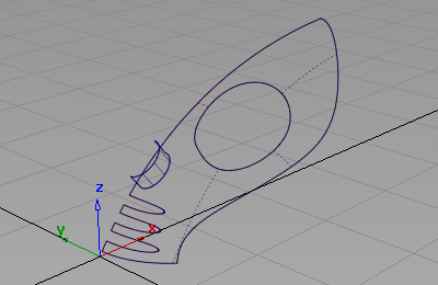
First create a cylinder surface for the outline of the power button.
- Return to the wireframe view using Diagnostic Shade in the Control Panel
- Choose Layouts > Top
 or the F5 hotkey to switch to the Top view.
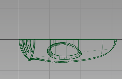
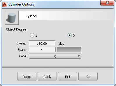
- Choose Surfaces > Primitives > Cylinder
 . Double-click the icon to open the cylinder options.
 - Set the Sweep to 180 and the Spans to 4 to create a half cylinder. Set the Caps to 0 from the drop-down menu, to create only the side wall of the cylinder.
Click the Go to create the half cylinder.
- In the Top view, hold down the
 (Windows) or
  (Mac) key to turn on grid snapping, and click near the origin. Snapping the cylinder on the origin ensures that it is centered.
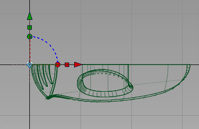
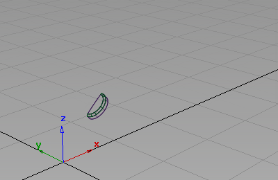
- With the cylinder still selected, choose Transform > Non-p Scale
 . Type 400,-300,200 and press
  (Windows) or
  (Mac) to scale the half cylinder to an oval shape, and to invert it so it is on the right side of the grid.
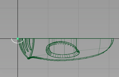
- Choose Layouts > Left
 to switch to the Left view.
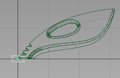
- Choose Transform > Move
 . Hold down the
  and (Windows) or
  and (Mac) keys to turn on curve snapping. Point the cursor at the top edge of the upper surface and click and hold down the
  . With the mouse button still pressed, drag the cylinder until it is roughly half way between the handle and the air vents.
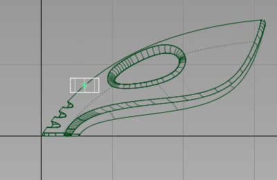
The cylinder moves along the edge.
- Choose Transform > Rotate
 and type 0,-40,0 to rotate the cylinder around the y-axis. Check that the cylinder is entering the upper surface at a good angle. If you need to adjust the angle further, drag using the
  to adjust the y-rotation.
- Choose Layouts > Perspective
 , or the F8 hotkey to return to the perspective view.
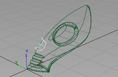
- Choose Pick > Nothing
 to deselect the cylinder.
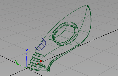
Create two surfaces for the button and the recess
Use the cylinder you created twice. First, use it as the sidewall of the power button, then use a second copy to create the sidewall of the recess in the main body.
Also use the upper surface twice. Use a copy to create the top of the power button. Trim most of the surface away. The part that is left is flush with the vacuum body.
Trim the original upper surface to create the recess for the button.
To avoid confusion with these copied surfaces, first create layers for the body surfaces, and for the power button surfaces.
- Choose Layers > New
 to create a layer.
- Rename the layer to body.

- Choose Pick > Object
 . Drag a pick box over all the geometry to select all the surfaces.
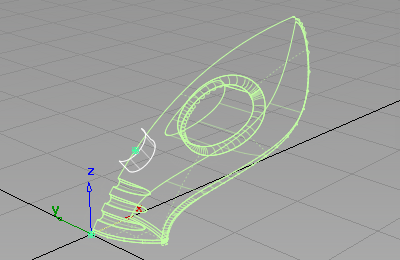
- On the Layer Bar, click and hold on the body layer to see the drop-down menu. Choose Assign to assign all the surfaces onto the layer.
- Choose Pick > Nothing to deselect all the surfaces.
-
Now create a second layer for the power button.
Choose Layers > New
to create a layer. 
- Rename the layer to power_button.

- Choose Pick > Object. Pick the half cylinder and the upper surface of the vacuum body.
- Choose Edit > Copy
 followed by Edit > Paste
 . The two surfaces are copied and left selected.
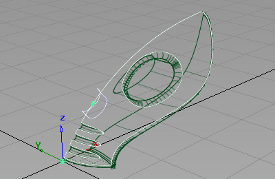
- On the Layer Bar, click and hold on the power_button layer to view the drop-down menu. Choose Assign to assign the two copied surfaces onto the layer.
You now have two copies of the cylinder and top surface, one on the body layer, and one on the power_button layer.
- Choose Pick > Nothing to deselect the surfaces.
Create the power button
Next use the copied surfaces to create the power button. Use the Surface fillet tool to trim and round the edge of the power button.
- On the Layer Bar, click the box beside the body layer to make the body surface invisible. This a shortcut to selecting Visible on the drop-down menu.
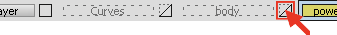
Only the two surfaces you copied are visible.
- Choose Surfaces > Multi-Surface Fillet > Surface Fillet
 (if you are using Alias Design, select Surfaces > Surface Fillet). Double-click the icon to open the option box.
 Change Construction Type to Radius and Center Radius to 20.
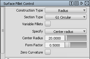
Close the Surface Fillet option window.
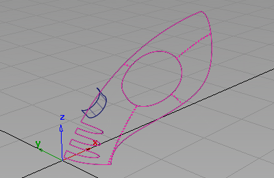
You are prompted to select the first set of surfaces.
- Click the upper surface to select it.
The surface is selected and highlighted in pink.
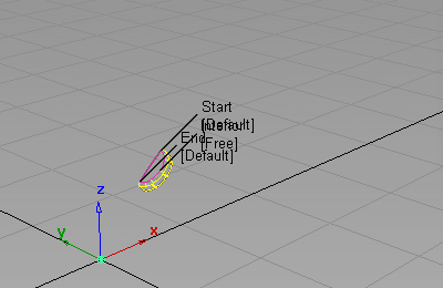
Select the second set of surfaces.
- Click the half cylinder surface to select it.
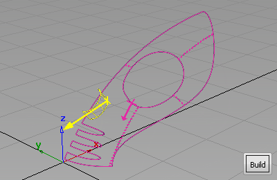
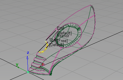
The surface is selected and highlighted in yellow, and a Build button appears in the bottom right corner of the view.
Arrows appear on both surfaces, indicating on which side of the surfaces the fillet will be built.
The pink arrow needs to point in towards the inside of the vacuum surfaces. If it is pointing out from the surfaces, click the arrow to reverse it.
The yellow arrow needs to point inwards on the cylinder surface. If it is pointing outwards, click the arrow to reverse it.
- Click Build.
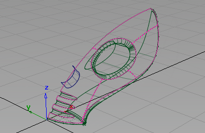
The fillet surface is created, and the upper and cylinder surfaces are trimmed to create the power button.
- Choose Pick > Nothing to deselect all the surfaces.
Create the power button hole
Next use the Surface Fillet tool to trim and round the edge of the power button recess.
- On the Layer Bar, click and hold on the power_button layer to see the drop-down menu. Choose Visible to make the power_button surfaces invisible.
- Make the body layer visible by clicking the box beside it.

- Make the body active by clicking the layer tab to make it yellow. All new surfaces are assigned to the active layer.

- Choose Surfaces > Surface Fillet. The settings you used before are used for this fillet surface so do not open the option box.
You are prompted to select input surfaces.
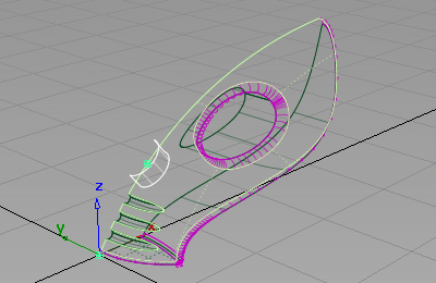
- Click the upper surface to select it.
The surface is selected and highlighted in pink.
- Click the cylinder surface to select it.
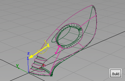
The surface is selected and highlighted in yellow, and a Build button appears in the bottom right corner of the view.
Arrows appear on both surfaces, indicating on which side of the surfaces the fillet will be built.
The pink arrow needs to point in towards the inside of the vacuum surfaces. If it is pointing out from the surfaces, click the arrow to reverse it.
For the recess, create the fillet on the other side of the cylinder, so ensure that the yellow arrow points outwards on the cylinder surface. If it is pointing inwards, click the arrow to reverse it.
- Click Build.
The fillet surface is created, and the upper and cylinder surfaces are trimmed to create a recess for the power button.
 Note:
Note:Because the direction of the yellow arrow is different for this second fillet, the result is different from the filleting of the power button.
- Choose Pick > Nothing to deselect the fillet surface.

- Make the power_button layer visible by clicking the box beside it.
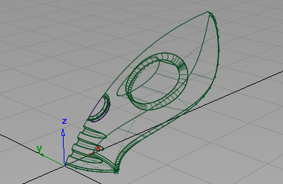
You have now completed the main vacuum cleaner body surfaces.
Save your work
- Choose File > Save As
 to save the current scene.
 - Save your work in the wire folder of the Lessons project.
- Name your file myvacuum6.wire.