Aligns a curve or surface edge to another curve, or surface edge. Also aligns an edge to the interior of a surface.
This Align tool was introduced in AliasStudio 2009 and is intended to replace the older version of the tool now called Align 2008.
Procedures
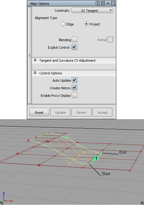
Align Options
- Continuity
-
Continuity level between the aligned geometry: G0 Position, G1 Tangent, G2 Curvature, or G3 Curvature.
- Alignment Type
-
Edge – This option is the default and provides alignments for all surfaces when a vector constraint is not used. This includes the alignment of a surface to a surface edge, isoparm, or curve-on-surface (CoS).
Project – This option aligns an edge to a surface by using a projection vector (along the current view by default). It is not necessary to have a curve-on-surface already on the surface to align to it. The curve-on-surface is created automatically.
 Note:
Note:If Project is selected, a Vector Options section appears to let you define a vector. The default vector direction is based on the current view. (See Vector Options.)
U/V – This option only appears when aligning a curve to a surface.
The curve is aligned to either the U or V direction of the surface.
Vector – This option only appears when aligning a curve to a surface.
The tangent and curvature alignment is defined by the tangent plane to the surface at the point of contact, and the direction of the vector specified through Vector Options. That is, the tangent and curvature CVs on the curve are only allowed to move in the direction of the vector. This is the equivalent to creating a curve-on-surface on the surface, and aligning the free curve to it.
If the vector is set to View, the shape of the curve in the given view remains the same through the alignment, while maintaining the desired level of continuity with the surface.
- Vector
-
This checkbox is only available when aligning a surface to another surface with Alignment Type set to Edge and Continuity set to G1 Tangent or G2 Curvature.
When Vector is checked on, positional continuity is achieved first, then the tangent and curvature CV rows are constrained to move along the selected vector. (See Vector Options.)
- Tangent Balance
-
This option is only available when Continuity is set to G1 Tangent, G2 Curvature, or G3 Curvature and the following conditions apply:
- Both the Input and Master are surfaces
- You are aligning to a natural boundary (not a trim edge or curve-on-surface)
- Outer edges are both set to Edge Align
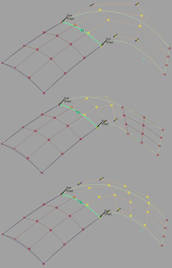
When Tangent Balance is checked on, the CVs of the tangent row are adjusted so that the ratio of the start and end tangent lengths on the Input surface matches that of the Master. If G2 Curvature or G3 Curvature is on, the same applies to the respective curvature row CVs (second and third rows from the edge). The inside CVs are also adjusted so that the Input’s hull (for the tangent and curvature rows) mimics the shape of the Master’s.
Tangent Balance is off.
Tangent Balance is on. The hull shape of the Input reflect that of the Master.
The tangent and curvature lengths can be scaled in a proportional way so as not to change the shape of the Input surface, by using the Tangent Scale, Curvature Scale, and G3 Scale sliders (or corresponding manipulators). These sliders are only available when Tangent Balance is on, but retain their values if Tangent Balance is toggled off then on again.
- Blending
-
This option applies to both Input curves and surfaces. It moves the inner rows of CVs to even out the modification in the Input. You can adjust the number of Extra CV Rows that get modified and the Blend factor to get the desired effect. The rows of CVs needed to maintain continuity are not touched.
- Partial
-
The Partial checkbox is always off by default when a surface is aligned. Initially, the input surface’s edges are aligned to the full extent of the master’s edge. If Partial is turned on, the closest points on the master surface’s edge (or curve) are used.
The Partial Join manipulators are always displayed. Use the manipulators (or the Partials sliders) to control the extent. The Partial option applies when a surface edge is aligned to another surface edge, isoparm, curve-on-surface, or free curve
Partial is turned off automatically if the manipulators are dragged to the ends of the master’s edge. It is turned on automatically when the manipulators are dragged away from the ends.
Turning on Partial always resets the manipulators to the closest points on the master’s edge. Conversely, turning off Partial sets the manipulators to the ends of the master's edge.
- Explicit Control
-
Checking on this option gives you access to the Explicit Control Settings where you can adjust the degree and number of spans for the Input. These settings only appear once both the Input and Master geometries have been selected. The degree and span settings initially correspond to those of the Input curve or surface.
Increasing the degree or adding spans can provide greater flexibility for the curve or surface to align to continuity, or create a more subtle blend. Explicit Control is checked on by default.
If Explicit Control is not checked, the alignment will first raise the degree of the Input to match that of the Master, before attempting to insert spans to achieve continuity.
- Position Influence
-
This slider only appears when Alignment Type is set to Edge and Vector is off.
When Position influence is set to 0.0 (default), the alignment process attempts to maintain the parameterization of the Input surface. This alignment will not cause any CV movement provided the fit is already within the Curve Fit Distance tolerance. If the edge needs to be refit, there may be minimal CV movement.
When Position Influence is set to 1.0, the alignment attempts to match the parameterization of the Input surface to the parameterization of the Master as closely as possible. This alignment has more freedom to produce a closer fit (better continuity), but can cause the lateral spacing of position, tangent, and curvature CVs on the Input to change. However, tangent and curvature lengths are not affected by Position Influence.
Note:This sometimes results in the CV structure of the Input conforming itself to the Master’s, typically when both edges have the same degree and number of spans.
The slider provides for incremental interpolation between maintaining parameterization on the Input and providing continuity with the Master.
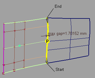
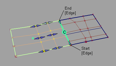
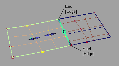
Position Influence = 0. Positional continuity not achieved.
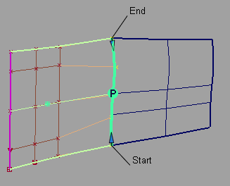
Position Influence = 1.0. Positional continuity achieved.
Blending Options
- Extra CV Rows
-
Number of CV rows affected by the blending. These rows are located beyond the rows of CVs needed to maintain continuity, which are not touched.
- Blend factor
-
The degree to which the influence of the alignment decreases or increases as it moves out to the extra CV rows. (This option is only available if Extra CV Rows is greater than zero.)
A positive value indicates that the influence decreases exponentially. The higher the value, the more rapidly the influence drops.
A zero value indicates no drop in influence; the change is constant row by row.
A negative value indicates that the influence increases exponentially. The higher the absolute value, the more rapidly the influence increases.
Vector Options
- X,Y, Z
-
Select one of these options to specify a vector along that axis.
- View
-
Select this option to specify a vector normal to the current view. The vector is not drawn in the view windows.
If the current view is changed, click Refresh Vector to update the vector.
- Picked
-
Selecting this option lets you specify the name of an existing vector in the Picked Vector field, or pick the vector in the view.
- Normal
-
The alignment is done by moving the CVs along the surface normals instead of using a single vector direction.
- Refresh View Vector
-
This button only appears if View is selected. Click it to update the vector if the view has been modified.
- Retain Vector
-
Click this button to create a vector construction object in the view windows. If you do not click this button, the tool uses the vector direction you specified, but you are not able to see and re-use the vector.
Note
Every Align workflow that requires specifying a direction through the Vector Options uses the X, Y, and Z axes from the construction plane, if one is set.
The following rules apply:
- Projections always respect the current coordinate system.
- If a projection was made in one set of coordinates (construction plane), and is later query-edited in a different one, the Refresh Vector button in the control window can be clicked to update the projection.
- If a construction plane is moved after creating a projection, nothing happens automatically. If the surface is query-edited later, the Refresh Vector button lets you refresh the projection.
Projection Align along Z in global coordinate system
After setting a construction plane and clicking Refresh Vector, the projection is updated.
Explicit Control Settings
- U Degree
-
Degree of the Input surface in the U direction.
- V Degree
-
Degree of the Input surface in the V direction.
- Degree
-
Degree of the Input curve.
- U Spans
-
Number of spans on the Input surface in the U direction.
- V Spans
-
Number of spans on the Input surface in the V direction.
- Spans
-
Number of spans on the Input curve.
Outer Edge
The following section only appears when Alignment Type is Edge, and Continuity is set to G1 Tangent, G2 Curvature, or G3 Curvature.
These options control the direction of the tangent (within the tangent plane) along the outer edges of the Input surface.
- Align Start/End Together
-
When this box is checked, the setting for Start Align and End Align is kept the same.
- Start Align/End Align
-
Edge Align – The edge is aligned to either the natural boundary or to a trimmed edge.
Skew – The edge is rotated by the specified Skew Angle while remaining in the tangent plane.
Click the label in the view window to toggle between Edge Align and Skew.
- Start Skew Angle/End Skew Angle
-
The angle of rotation (in degrees) of the start or end outer edge.
These values can also be adjusted by using the small circle manipulators in the view windows.
The following section only appears when Continuity is set to G1 Tangent, G2 Curvature, or G3 Curvature.
These options control the length of the tangent or curvature. You can also use the tangent and/or curvature manipulators to adjust those values.
Tangent and Curvature CV Adjustment
- Starting Tangent Scale/Ending Tangent Scale
-
These slider values let you adjust the true lengths of the tangents (in centimeters) along both edges of the Input surface.
- Tangent Scale
-
This slider value lets you adjust the true length of the tangent (in centimeters) at the aligned end of the Input curve.
When aligning surfaces, if Tangent Balance is on, this slider lets you scale the tangent lengths in a proportional way, so as not to change the shape of the surface. It retains its value if Tangent Balance is toggled off then on again.
- AutoScale G2
-
If Continuity is set to G2 Curvature, this option adjusts the G2 curvature automatically while you scale the tangent. It attempts to maintain the same relative arm-lengths, that is, position-row to tangent-row versus tangent-row to G2 curvature-row, as in the unaligned surface (or curve).
If Continuity is set to G3 Curvature, this option adjusts both the G2 and G3 curvature automatically while you scale the tangent. It attempts to maintain the same relative arm-lengths as in the unaligned surface (or curve).
Note: AutoScale G2 and AutoScale G3 are mutually exclusive. - Starting Curvature Scale/Ending Curvature Scale
-
These slider values let you adjust the true G2 curvature lengths along both edges of the Input surface.
- Curvature Scale
-
This slider value lets you adjust the true G2 curvature length at the aligned end of the Input curve.
When aligning surfaces, if Tangent Balance is on, this slider lets you scale the G2 curvature lengths in a proportional way, so as not to change the shape of the surface. It retains its value if Tangent Balance is toggled off then on again.
- AutoScale G3
-
Adjusts the G3 Curvature automatically while you scale the G1 Tangent or G2 Curvature. It attempts to maintain the same relative arm-lengths, that is, tangent-row to G2 curvature-row versus G2 curvature-row to G3 curvature-row, as in the unaligned surface (or curve).
Note: AutoScale G2 and AutoScale G3 are mutually exclusive. - Starting G3 Scale / Ending G3 Scale
-
These slider let you adjust the true G3 curvature lengths along both edges of the Input surface.
- G3 Scale
- This slider lets you adjust the true G3 curvature length at the aligned end of the Input curve.
Partials
- Start / End
-
These sliders values range from 0.0 to 1.0 and specify the percentage of the way that the start or end of the Input surface extends from the end of the Master surface (in parameter space).
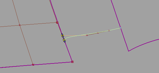
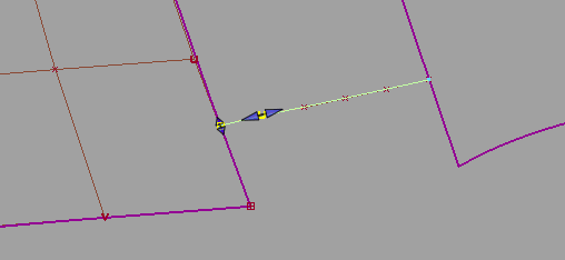
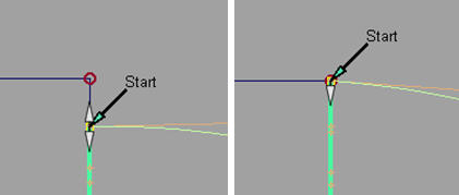
These values can also be adjusted by using the Partial slider manipulators along the boundary. The manipulators indicate they have been positioned at the full extent of the edge of the Master by displaying only the internal arrow. Double arrows indicate that the Input edge is not positioned at the full extent of the edge of the Master.
The Partial slider manipulators also snap to the options set in the Snap Options window (except for Snap to Center and Pivot).
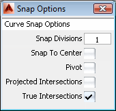
See Curve Snap Options.
Attach Point
This section applies to curve alignment only.
- Attach Point
-
Point on the Master curve that the Input curve is aligned to. The slider value ranges from 0.0 to 1.0 and specifies the percentage of the way from the start of the Master curve.
Control Options
- Create History
-
Saves the construction history of the alignment so you can edit the aligned objects or the tool options and the alignment automatically updates.
Note:When a curve or surface is aligned to two masters, it only has a single history item.You can still edit both Align operations separately by using Object Edit > Query Edit and clicking near the appropriate end/edge of the aligned geometry.
- Auto Update
-
Automatically recalculates the alignment as you change the controls in the window.
- Continuity Check
-
Adds a surface continuity locator to the aligned edge, giving a pass/fail indication on continuity and showing any discontinuities.
- Specify Check/Continuity Check Type
-
Turn Specify Check on to show the Continuity Check Type option, which allows you to check for a specific level of continuity.
When Specify Check is off, the tool checks for the continuity you specified for the alignment (with the Continuity option).
These options appear when Continuity Check is on.
- Enable Proxy Display
-
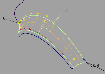
Check on this option to see the hull of the original input surface (surface being aligned) as a green proxy. This proxy helps you visualize how much the surface has changed during the Align operation.
If you click Accept to "store" the current state of the Align operation, the modified input surface becomes the new original surface. The proxy display updates to reflect this fact.
Note: If the CVs and hull of the input surface are hidden, turning on Enable Proxy Display makes them visible.
Buttons
- Reset
-
Restores your saved settings. If you have not saved custom options, Reset restores the installed option settings.
- Update
- If Auto Update is off, click this button to recalculate the alignment and update the model in the view.
- Revert
-
Click this button to cancel all changes to the Input and return it to its original shape, as if the tool was never invoked. All history is deleted.
Note:When a curve or surface is aligned to two masters, Revert first reverts the active side. The history then applies only to the remaining side. Clicking Revert again deletes the history and returns the input geometry to its original shape.
- Accept/Restore
-
Each time the Accept button is clicked, a configuration of the tool and the current Input geometry is saved.
The Restore button is only available when the Accept button has been clicked at least once. Each time the Accept button is used, the state is stored, and can be retrieved by using the Restore button. This way, it is possible to append a series of alignment operations.
Edit > Undo (![]() +Z (Windows) or
+Z (Windows) or ![]() +Z (Mac) ) can be used multiple times to restore modifications to the scaling of tangency, curvature, or partial edge location. Undo lets you explore modifications and still return to a preferred alignment. Undo cannot be used immediately after clicking Accept or Restore.
+Z (Mac) ) can be used multiple times to restore modifications to the scaling of tangency, curvature, or partial edge location. Undo lets you explore modifications and still return to a preferred alignment. Undo cannot be used immediately after clicking Accept or Restore.
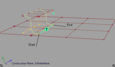
Using the manipulators
- Position of Attach Point on curves
- Tangent length, G2 curvature, and G3 curvature length along the outer edges, when Tangent Balance is off. A center manipulator lets you keep the existing length ratio between both ends (akin to “sliding” the hull).
- Skew angles on the outer edges.
- Tangent scale, curvature scale, and G3 scale for surface alignment when Tangent Balance is on, so that all tangent and curvature lengths on the input surface are scaled proportionally, to maintain the surface shape.
- Partial join manipulators. These change from double to single arrows when snapping to the edge of the Master surface.
The manipulators appear as small arrows or double arrows, except for Skew which is an arc with a small circle. Once the manipulator is engaged by clicking the arrow or circle, mouse contact is not required to make further modifications.
The following values can be adjusted directly through manipulators:
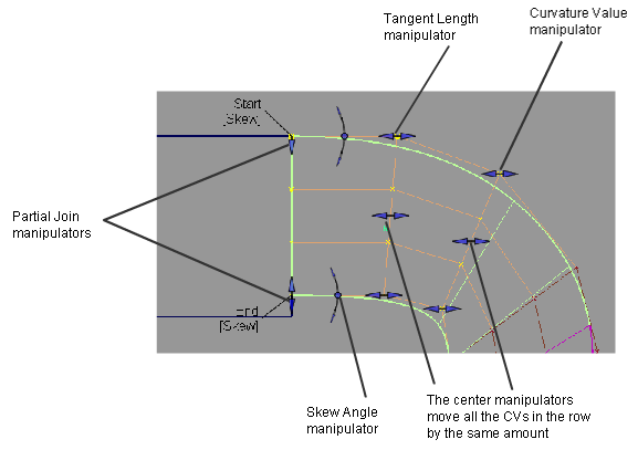
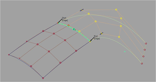
Surface alignment manipulators
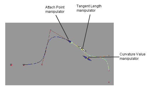
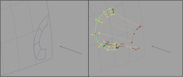
Curve alignment manipulators