- On the ribbon, click
Sketch tab
 Format panel
 Construction
to reset your geometry creation to normal geometry.
 - Next, click
Sketch tab
 Draw panel
 Line
, or right-click and select Line from the marking menu.
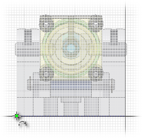
 - In the graphics window, move your cursor over the lower-left corner of Cylinder Base.ipt until you see the green circle. It indicates that you are over the endpoint of the construction line that you previously projected.

- Click to place the first point of your line.
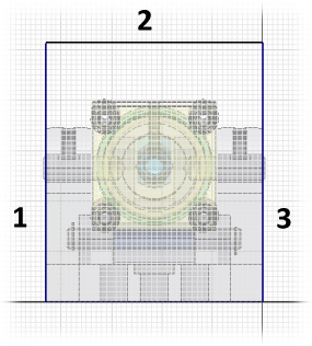
- Paying attention to the vertical and horizontal constraint indications, place three line segments: vertical, then horizontal, and then vertical again. Beginning the new segment from the end point of the previous segment ensures that the lines form a single, continuous open profile. Your profile should appear as in the following image:
 Note: To determine the horizontal endpoint on the right end of segment 2, drag your cursor down to locate the right end point of the construction line that you projected earlier and then move your cursor upwards vertically maintaining that alignment. The lower endpoint of segment 3 should be coincident with the right endpoint of the projected construction line.
These three lines represent the inside faces of the Contour Flange that creates the base feature of the sheet metal guard.
- Click
Sketch tab
 Constrain panel
 Dimension
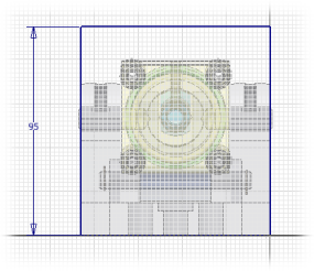
, or right-click and select Create Dimension from the marking menu. Now, place a vertical dimension of 95 mm to define the height of the guard. Both vertical line segments adjust due to the horizontal constraint that was created when segment 2 was placed.
- Click
Sketch tab
 Exit panel
 Finish Sketch
, or right-click and select Finish 2D Sketch to exit the sketch environment.
Next, you create the Contour Flange using the open profile sketch you just created.