Before you create the Contour Flange, check the Sheet Metal Defaults.
Note: Complete the Sheet Metal Styles tutorial (when you have time) to understand the inter-relationships between the Materials, Sheet Metal Rules, and Sheet Metal Unfolding Rules. By correctly establishing a set of Sheet Metal Rules for your work, and ensuring that these rules are set as the default in your Sheet Metal.ipt template, you will be able to begin sheet metal design projects without editing the Sheet Metal Defaults each time you start a new part design.
- On the ribbon, click
Sheet Metal tab
 Setup panel
 Sheet Metal Defaults
, or right-click and select Sheet Metal Defaults from the marking menu.
 - Take note of the following items:
- Name of the Sheet Metal Rule
- State of the check box for Use Thickness from Rule
- Value in the Thickness field
If Use Thickness from Rule is checked, and the value in the Thickness field is something other than 2 mm, click the check box to remove the check.
- The Thickness field is now enabled. Enter 2 mm to replace the value in this field.
- Click OK to apply the 2-mm thickness to the current model file.
Note: These steps allowed you to override the material thickness declared by the active Sheet Metal Rule. In most cases, you begin your designs using a template that has an appropriate Sheet Metal Rule active. Or, you previously created Sheet Metal Rules for your work that you can select from the drop-down list of Rules available in the shared Styles and Standards library.
Now, you can create the Contour Flange.
- On the ribbon, click
Sheet Metal tab
 Create panel
 Contour Flange
.
 - In the graphics window, click over the three-line sketch that you previously completed. Note that the 2-mm thickness of the sheet metal Contour Flange is previewed, and that it is offset to the inside.
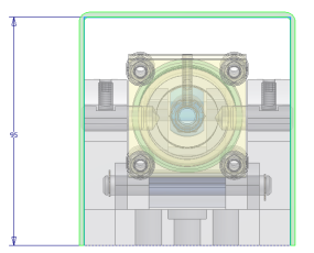
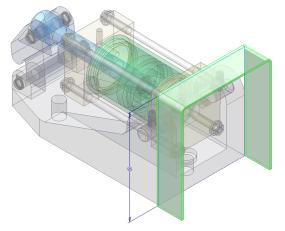
- In the Contour Flange dialog box, click the Flip Side option. The 2-mm material thickness should now be offset to the outside of the profile, as shown in the following image:

- With the Contour Flange dialog box active, adjust your view (using either the View Cube or Orbit) to see the side of the model as follows:

Next, you change the flange creation direction and measure an existing edge to complete the creation of the Contour Flange.