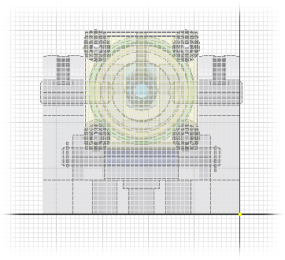
Note: All sketch illustrations in this tutorial show the grid displayed. If you have recently completed either the Parts 1 or Parts 2 tutorials, your sketch grid is undisplayed by changing the Application Options. This tutorial does not require the use of the sketch grid and can be completed with the grid displayed or undisplayed.

While creating a part within an assembly, you are able to see and reference the other parts in the assembly. By default, when you reference geometry in another part, you get an associative relationship to that part. If the original part changes, the geometry that you created also changes to honor the association. In this tutorial, you use an option to reference the geometry without creating the associative reference. In situations where you are certain there will be no further design changes, not creating an associative relationship improves subsequent assembly recompute performance.
- On the ribbon, click
Sketch tab
 Format panel
 Construction
to ensure that the line you project is “construction” geometry that will not be used for feature creation.
 - Next, click
Sketch tab
 Draw panel
 Project Geometry
, or right-click and select Project Geometry from the marking menu.
 - While holding down the Ctrl key on your keyboard, click the lower edge of Cylinder Base.ipt as shown:

Note: Holding down the Ctrl key while projecting geometry breaks the associative link that would normally be obtained.
Next, you create a simple, three-line sketch that represents the inside faces of the Contour Flange. It will create the basic shape of the guard.