While there are several ways to create circular holes in your sheet metal part, using a round Punch feature provides you with annotation benefits when you detail the flat pattern of your design.
Note: This tutorial uses an example Sheet Metal Punch iFeature that contains the two punch sizes required by this tutorial. The IDE file that contains this punch is located in the default project folder that is active when the tutorial_files project is active. To learn more about Sheet Metal Punch iFeatures, please review the Skill Builders posted to: http:\\www.autodesk.com\inventor-skillbuilder These sheet metal Skill Builders can be found by clicking on the Parts heading.
- On the ribbon, click
Sheet Metal tab
 Modify panel
 Punch Tool
.
 - The Punch Tool Directory dialog box opens. By default, it displays Punch Tools that are stored in the Punches folder, which is located in the Catalog folder under the default installation folder. Click Workspace in the navigation panel on the upper-left side of the Punch Tool Directory dialog box to switch to the Tutorial Files folder.
- Select Cylinder Clamp
 metric_hole.ide, and click Open to display the Punch Tool dialog box.
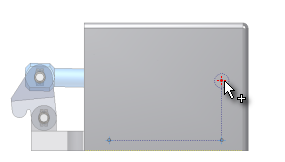
 - The example file includes punches of two different sizes; however, the 2.5-mm diameter punch is previewed on the three center points in the displayed and unconsumed sketch. While the 2.5-mm diameter punch is needed on two of the center points, you must first clear the center point that will be used for the 12-mm punch. While holding the Shift key, move your cursor over the center point as shown, and click to clear the center point.

- Click Finish in the Punch Tool dialog box to place the 2.5-mm diameter punch on the remaining two center points and close the dialog box.
Next, you follow a similar set of steps to place the 12-mm diameter punch.