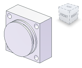
In this section, we create a revolved feature using projected model edges.
Projected edges help “anchor” the geometry to the model when no edges are projected. Use the Revolvecommand to create cylindrical shapes quickly.
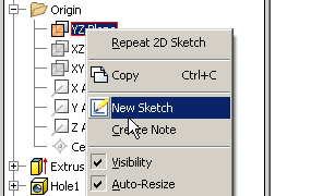
- Expand the Origin folder in the browser, right-click on the YZ Plane, and select New Sketch from the context menu. Turn Visibility on to view the YZ Plane in the graphics screen.
- Right-click in the graphics window, and select Slice Graphics from the overflow menu, or choose F7 to toggle Slice Graphics on and off.
Navigate to a plan view using the ViewCube (use Right, for example.).
-
 Select Project Geometry to copy a parallel model edge to the sketch in the center of the part.
-
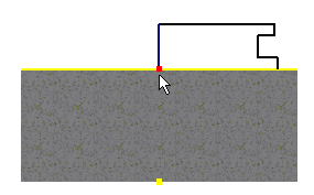
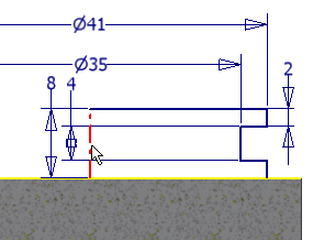
 Start the Line command and begin to sketch a shape. Start with a vertical line from the midpoint of the projected geometry. A green dot indicates the midpoint. Tip: An explicit horizontal line on the lower section of the sketch is not required to create a closed shape. Inventor uses Coincident constraints to determine closed boundaries. If the two vertical lines are attached to the projected edge of the sketch with Coincident constraints, there is no need to draw the line.
-
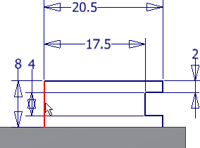
 Dimension the sketch as shown in the following image. Apply a Collinear constraint to the outer vertical edges as shown in the following image. It enables both lines to be controlled by the same dimension. All sketch elements change color to indicate that the sketch is fully constrained. Tip: If the sketch is not fully constrained, one or both of the outside vertical lines are probably not attached to the projected line. Apply coincident constraints to attach the ends (indicated by the arrows in the following image) to the projected line. You can also apply a coincident constraint using a drag operation to connect elements.
-
 Finish the sketch.
 -
 On the Model tab, select the Revolve command. The closed boundary sketch profile you just completed should already be highlighted. If not, select it. Next, the highlighted axis button in the mini-toolbar prompts you to pick an axis to revolve around. Pick the center line.
  Tip:
Tip:- If you define the axis line as a centerline, Autodesk Inventor selects the axis for you. Define the axis as a centerline to dimension the diameter when you dimension from the centerline to an outer edge.
- To designate the central axis as a sketch centerline, you must be in the Sketch environment. Select the axis, and then choose the centerline icon on the Format panel of the Sketch tab.

Finished shape -
