In the next section, we will create a hole using offset sketch geometry to determine hole placement. After we create the hole, we will use the rectangular pattern command to create additional holes.
There are several reasons to use a hole instead of an extrusion with the cut option:
- Using a Hole command instead of an extrusion with a cut provides more control over the part feature.
- Patterning a feature allows associative placement of mating components in an assembly. Assembly Components placed on a part feature pattern determine the count and spacing from the part feature.
- The drafting environment contains a hole note command which can associatively extract all the details of a hole.
To begin:
-
 Start a sketch on the part face using one of these methods to start a new sketch (the second option is the most direct and offers the least amount of mouse movement).
 - On the ribbon, click
3D Model tab
 Sketch panel
 Create 2D Sketch
, and then select the part face to sketch on.
 - Select the face to sketch on. When the mini-toolbar appears, click the third button on the right labeled with the tooltip, Create Sketch.

- Select the face to sketch on, then right-click and select New Sketch from the marking menu.
The edges of the extrusion are copied to the current sketch.
Tip: The icons for 2D Sketch and 3D Sketch are similar. They provide two different sketching environments. If you start a 3D sketch, perform an Undo and start a new 2D Sketch. - On the ribbon, click
3D Model tab
-
 On the ribbon, click
Sketch tab
 Modify panel
 Offset
.
 - Select one of the edges, then drag it to the inside, and click to place. All edges highlight and drag. If all the edges do not highlight, right-click and make sure Loop Select and Constrain Offset are checked in the overflow menu, then retry the selection.
- Enable Loop Select to allow all planar continuous sketch geometry to be selected as a group. Disable to select individual edges.
- Enable Constrain Offset to apply automatic constraints which allow one offset distance to determine the position for the entire selection. Disable to allow each edge to be dimensioned independently.
-
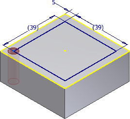
 Start the Dimension command. Dimension the offset geometry 5 mm away from a feature edge.
 - Place a horizontal and vertical dimension on the two edges of the offset geometry. The horizontal and vertical dimensions appear in parentheses as reference (driven) dimensions. These dimensions will be used later to extract the spacing in the feature pattern. Note: If you receive a warning when you dimension the offset sketch geometry, choose Accept to create a driven dimension. This message appears if you did not choose Apply driven dimension in the Application Options
 Sketch tab.
 -
 Finish the Sketch.
 -
 Click
3D Model tab
 Modify panel
 Hole
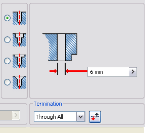
, or select Hole from the marking menu. Set the Placement option to From Sketch. Select the lower left vertex in the offset sketch to position the hole. Set the hole diameter to 6 mm and the termination to Through All, then choose OK to create the hole.

The sketch is “consumed” under the hole feature in the browser.
- To select the 39-mm sketch reference dimensions for the hole pattern spacing, they must be visible. Locate the hole feature in the browser, and click + to expand and show the sketch. Right-click the sketch, and choose Visibility from the context menu.
-

-
 Click
3D Model tab
 Pattern panel
 Rectangular
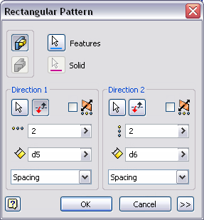
. The Features selection arrow is selected. Pick the Hole. If you are viewing the hole in a plan view, it is difficult to select the hole on the part. Rotate the view slightly in 3D before selecting the hole on the part. You can also select the hole directly in the Model browser. Attention: Do NOT select the extruded body, or it will be patterned with the hole.
 - Pick the Direction 1 arrow, and then choose a horizontal edge to set the direction. The edge you choose determines the initial direction.
For example, if you choose the lower model or sketch edge, the horizontal pattern direction is to the left. If you choose the upper model or sketch edge, the horizontal pattern direction is to the right.
 Use the Flip direction arrow to reverse the direction. Set the count to two, and then highlight the text in the dimension spacing field. With the text highlighted, select the horizontal sketch dimension to use the dimension value for the spacing. Pick the Direction 2 arrow, and then pick a vertical model or sketch edge. Set the count to two, and then highlight the text in the dimension field. Select the vertical reference dimension to use the dimension value.
- Click OK to create the pattern. After you create the pattern, right-click Sketch2 in the Model browser, and turn off the sketch Visibility.