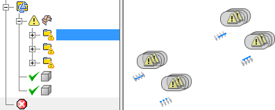
- In the browser, turn on the visibility of the composite surface with errors.

- Expand the composite surface browser entry to display the error types and quantity. Click an error folder or an individual error to cross highlight in the graphics screen. The mounting tabs contain many errors.

 In the ribbon, click the Heal Errors command.
 - Select the composite body in the browser or the graphics window.
The Heal Errors dialog box displays that 64 errors are found in the body. Do not change the default Allowable Change tolerance.
 Click Analyze Selected Bodies.
 When the analysis finishes, the dialog box displays 12 Errors fixed at this allowable change.
- Click OK to heal the errors that can be fixed at this tolerance.
 Click Finish Repair to exit the environment.
Some of the errors in the mounting tabs are the result of failed fillets to the table body. Others are the result of loose modeling practices. In this example, manually fixing the remaining errors is time consuming and offers little benefit. In this tutorial, feature creation commands are used to create a single editable replacement. The pattern and mirror commands are then used to create all the necessary mounting tabs.
- Expand the Solid Bodies folder, and turn on the visibility of the table stand. Examine the orientation of the mounting tabs in relation to the stand. Note: When you exit the repair environment, solid body visibility is controlled from the Solid Bodies folder.
- Expand the Origin folder.
- In the display tool, click View Face and then click the XY Plane in the Origin folder.

The stand is near vertical in the Y direction, but the mounting tabs have a slight angle. We can ignore the angle of the mounting tabs in this direction.

- Click View Face and then pick the YZ Plane in the Origin folder. Although the stand has a slight bow in this direction, a simplified mounting tab with a single hole is created for all features.
- After you pattern the first four tabs, start a new sketch on the face of each tab.
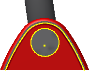
- Use Project Cut Edges to reveal the exact location the tube passes through each tab.

- You can then use the projected geometry or create a slightly larger profile and extrude it to create the cut.
- Use the mirror command to complete the remaining 12 tabs.