Lists the sheet metal unfolding rules in the active document or global style library (depending on the filter setting of Local or All Styles). Specifies unfolding method (linear or bend table) as well as units, backup KFactor value and bend table tolerances.
Access
Click
Manage tab
 Styles and Standards panel
 Styles Editor
![]()
In the browser pane, click Sheet Metal Unfold, and then click the sheet metal unfold style name to display the selections and values used while unfolding in the right portion of the dialog.
![]() Click the expand/collapse “+” to the left of the Sheet Metal Unfold entry in the left-hand portion of the Style and Standard Editor dialog box to display the list of existing rules. Select an existing sheet metal unfold rule to display its option settings.
Click the expand/collapse “+” to the left of the Sheet Metal Unfold entry in the left-hand portion of the Style and Standard Editor dialog box to display the list of existing rules. Select an existing sheet metal unfold rule to display its option settings.
- Back
-
Return to the previously edited style. You are prompted to save the previous edits.
- New
-
Create new styles. Select the Add to Standard check box to add to the available styles list in the active standard style.
- Save
-
Save changes to an existing style in the current document.
- Reset
-
Return style values to the saved values.
- Location Filter
-
Show Local Styles or All Styles (from the library) in the browser.
- Unfold Method
-
Dropdown selection specifies one of three unfold method options. The option selected will determine the options, attributes and controls that are displayed as described in the following sections:
-
Linear
- KFactor Value
-
Data entry field that allows the value of KFactor to be specified. The allowable range is from 0 to 1. The bend allowance is calculated using the following equation:
- Unfolded length = (inner Bend Radius + KFactor*Thickness)*(2*PI*Bend Angle/360) bend angle in degrees OR
- Unfolded length = (inner Bend Radius + KFactor*Thickness)*(Bend Angle) bend angle in radians
- Spline Factor Value
-
Data entry field that allows the value of Spline Factor to be specified. This value defaults to 0.5 and will impact the flattened sizes of Contour Flanges, Contour Rolls or Lofted Flanges with elliptical or spline segments within the feature profile (as well as the length of any non cylindrical or conical bend). Adjust the value up or down to more closely represent your manufacturing requirements.
-
Bend Table
- Linear Unit
-
Selection dropdown to define the units of the bend table from the following list:
- cm - Centimeters
- ft - Feet
- in - Inches
- m - Meters
- micron - Microns
- mm - Millimeters
- yd - Yards
- Thickness
-
Single column table which lists existing thickness entries followed by a hyper-text field that reads: Click here to add, which when clicked allows entry of a new thickness value. If no thickness values have been added the hyper-text field: Click here to add is displayed allowing entry of a thickness value when clicked.
- Backup KFactor Value
-
Value passed to the internal solver if a request falls outside of the defined bend table.
- Spline Factor Value
-
Data entry field that allows the value of Spline Factor to be specified. This value defaults to 0.5 and will impact the flattened sizes of Contour Flanges, Contour Rolls or Lofted Flanges with elliptical or spline segments within the feature profile (as well as the length of any non cylindrical or conical bend). Adjust the value up or down to more closely represent your manufacturing requirements.
- Table Tolerance
-
Three edit fields which allow tolerance values to be entered for:
- Sheet - Single unitless value representing the upper and lower tolerance on the sheet material thickness.
- Min/Max Radii - Single unitless value representing the upper and lower tolerance on the bend radius values.
- Min/Max Angle - Single unitless value representing the upper and lower tolerance on the bend angle values.
- Export Table
-
Click this command to export the currently displayed bend table as an ASCII text (*.txt) file. If the current table is not yet saved, you are prompted to save the table first.
- Angle reference
-
Radio button option setting:
- Bending Angle Reference - Option specifies that bends are defined using the angle resulting from the outside face of the bend and the face owning the selected edge.
- Open Angle Reference - Option specifies that bends are defined using the angle resulting from the inside face of the bend and the face owning the selected edge.
- Bend Table
-
The current bend table is displayed as a grid of values. Each row contains bend deduction values for the bend angle identified in the left-most column. Columns to the right contain bend deductions for the bend radius value in the top-most row.
Individual cells in the bend table can be activated for edit by a single mouse click. Depending upon the selected cell, a right-mouse click displays a context menu which offers the following bend table-related selections:
- Best Fit - Adjust the width of the current column to display all characters in the cells of all rows in the column.
- Best Fit (all columns) - Adjust the width of all columns to display all characters in the cells of all rows.
- Insert Column - Insert a new column in the table to the right of the current column with a copy of all values.
- Delete Column - Delete the current column.
- Insert Row - Insert a new row in the table below the current row with a copy of all values.
- Delete Row - Delete the current row.
- Paste - Paste the contents of the clipboard into the current cell. Warnings of illegal values are shown when changing focus to another cell.
- Paste Table- Replace the contents of the current bend table with a bend table that was copied to the clipboard.
- Copy Table - Copy the contents of the current bend table to the clipboard.
-
Custom Equation
- Equation Type
-
Dropdown selection allowing:
- Bend Compensation
- Bend Allowance
- Bend Deduction
- KFactor
Each of these will support the calculation of the size of the bend zone using different equations. The type you will select will depend on which variable you can provide as input. For a complete description of the equations used please refer to individual sections in the Custom Unfold Equations topic.
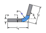
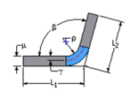
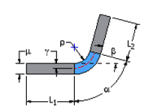
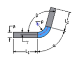
Each of these selections will display a variable listing and an image on the dialog box. The image displayed will depend on the equation type and angle reference.

Bend Compensation or Bend Deduction - Bending Angle

Bend Compensation or Bend Deduction - Open Angle

Bend Allowance or KFactor - Bending Angle

Bend Allowance or KFactor - Open Angle
- Angle reference
-
Dropdown selection allowing:
- Bending Angle Reference - Option specifies that bends are defined using the angle resulting from the outside face of the bend and the face owning the selected edge.
- Open Angle Reference - Option specifies that bends are defined using the angle resulting from the inside face of the bend and the face owning the selected edge.
Changing the Angle Reference will always change the image displayed on the dialog box.
- Equation Table
-
Three column table consisting of a header row and at least one row defining a custom equation and the bounding condition for that equation.
- Variable Column - The left-most table column contains the variable that is being defined by the equation. The variable displayed in the column is defined by the Equation Type selected and can not be edited in the table. This column has no label text in the header row.
- Custom Equation - This column contains the equation that will be used to solve for the variable in the left-most column for the bounding condition identified in the right-most column. Equations are entered into the table using the Equation Editor dialog box that is displayed following a double-click in the table cell.
- Bounding Condition - This column defines the upper and lower limits for which the equation in the middle cell is valid. Equations are entered into the table using the Bounding Conditions editor dialog box that is displayed following a double-click in the table cell.
Multiple rows within the equation table can be defined to specify unique solve conditions within a specific range of bounding conditions.
For additional details please refer to: Edit custom unfold equations or Edit custom unfold equation bounding conditions as appropriate.
- Backup KFactor Value
-
Value passed to the internal solver if a request falls outside of the defined equations.
- Spline Factor Value
-
Data entry field that allows the value of Spline Factor to be specified. This value defaults to 0.5 and will impact the flattened sizes of Contour Flanges, Contour Rolls or Lofted Flanges with elliptical or spline segments within the feature profile (as well as the length of any non cylindrical or conical bend). Adjust the value up or down to more closely represent your manufacturing requirements.
-
Linear
- Import
-
Use to import a material style exported from another document.
- Done
-
After saving changes, click to dismiss the Styles and Standard Editor dialog.