- On the ribbon, click
Annotate tab
 Table panel
, and then click the drop-down menu below Balloon.
  .
. - On the drop-down menu, click Auto Balloon.

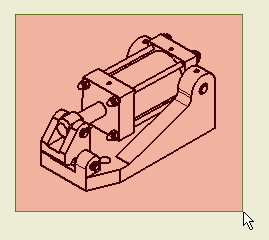
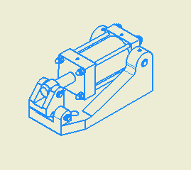
- Move your cursor over the isometric view of the assembly. When the view highlights with a red dotted boundary, click to select the view.
- Use the Balloon command to select individual components for ballooning. In this exercise, you select all the components in the view. Click above and to the left of the view geometry, and drag the mouse down and to the right. The pink rectangle should cover all the view geometry.

- Release the mouse button to select all the view geometry.

- Select the Around option in the Placement area in the Auto Balloon dialog box.
- Enter a value of 5 mm in the Offset Spacing field in the Auto Balloon dialog box.
- Click Select Placement in the Placement area in the Auto Balloon dialog box.

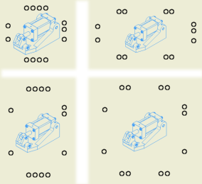
- Move your cursor into the drawing sheet. As you move your cursor, the balloons arrange themselves closer or farther away from the view center. Vertical rows move based on the horizontal position of the cursor relative to the view center. Horizontal rows move based on the vertical position of the cursor relative to the view center. The following illustration shows four possible balloon positions using the Around option.

- Move your cursor to a position that most closely resembles the display in the lower-right quadrant of the image shown above. When your balloon spacing appears similar, click to display the balloon arrows.
- Click OK in the Auto Balloon dialog box to accept and place the balloons and arrows.