In the next section, we create a spline profile and surface for another split tool.
- Start a new sketch on the bottom of the part.
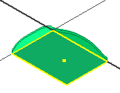
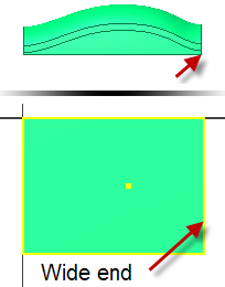
- Orient the part view as shown in the following image with the wide end of the part on the right.
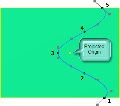
- Create a spline with five fit points as shown in the following image. Double-click the last point to create the spline. It is of no consequence if the handles on your spline do not match the image.
-
 Place a vertical constraint between the following fit points:
 - 1 and 5
- 2 and 4
-
 Place a horizontal constraint between fit point 3 and the projected origin point.
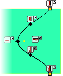
- Enable all linear handles on the spline using one of the following methods:
- Right-click and select Activate Handle in the context menu.
- Press and drag anywhere on a handle.
-
 Right-click the middle fit point and enable Curvature.
 - Place a vertical constraint on the handle at the midpoint and the two endpoints.
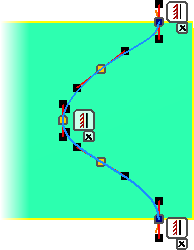
- Place a unitless dimension of 1 on each linear handle.
- Place a 12-mm radial dimension on the curvature handle at the middle fit point. It is of no consequence if your spline differs slightly from the following image.
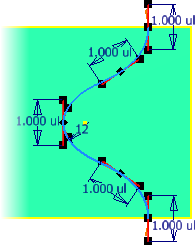
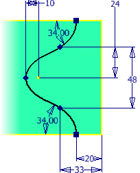
- Add an angular dimension of 34 degrees between the linear handles and the edges of the part as shown in the following image.
- Dimension the fit points as shown in the following image.
-
 Finish the sketch.
 -
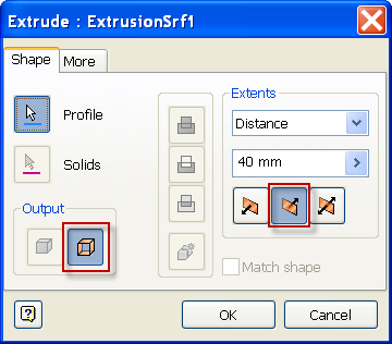
 Start the Extrude command. Set the Output to Surface and select the spline to satisfy the Profile selection. Set the Distance to 40-mm. Reverse the direction of the extrusion so the profile intersects the existing bodies. Click OK to create the surface.

- Save the file.