In this section, you define the parting surface for the mold assembly.
Creating a satisfactory parting surface is a crucial step in designing a successful injection mold. The right parting surface helps ensure that the design of the core and cavity suitable. The plastic part can be taken out of the mold. In Inventor Mold Design, the parting surface is divided into two parts: the patching surface and the runoff surface.
Patching surfaces are used to fill in all internal openings in a part, such as holes and slots. Many patching surfaces can exist in one part. The runoff surface is used to split the workpiece, and is also where the part is taken out of the mold. Only one runoff surface can exist on a part.
- On the ribbon, click Core/Cavity tab > Parting Design panel > Create Patching Surface
 . Select the Auto Detect button to detect all internal patches automatically and list them by name in the Creating Patching Surface dialog box. The patches are highlighted on the model in green.
 - Scroll through the list of patches and notice that 19 patches have been created. In some situations, the automatically detected patches create surfaces that are not suitable. Some patch surfaces may also be missing in the model. In this case, the largest opening is not patched correctly.
- Scroll to the top of the list of patches and click through the patch list until the patch that did not successfully patch the largest opening is highlighted. This patch is to be deleted. The opening will be patched manually.
- Right-click the patch in the Create Patching Surface dialog box and press Delete on the keyboard. A dialog box confirming the deletion appears. Ensure that large opening is selected and click Yes.
- Scroll to the bottom of the list and select Click to add. Patch 20 is added to the list.
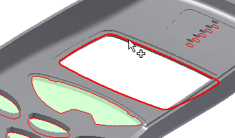
- Rotate the model and select the inside loop to patch the large opening as shown in the following image.

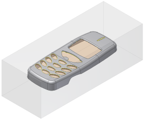
- Click OK to generate all patching surfaces. Click the Home view. The model appears as shown in the following image.

In real-world mold design sessions, you use a combination of automatic and manual surfacing to patch openings. In addition to using Click to add, you can also create manual patches with the Use Existing Surface or Create Planar Patch commands. Click the following link to open an animation that shows creating patching surfaces manually using these two workflows.
 Manually generating patching surfaces
Click the play button in the following image to play an animation that shows creating patching surfaces manually.
- On the ribbon, click Core/Cavity tab > Parting Design panel > Create Runoff Surface
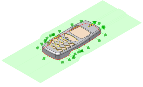
 . Click Auto Detect to generate a preview of the runoff loop as shown in the following image.
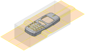
- Click OK on the Create Runoff Surface dialog box to accept the default surfaces.
