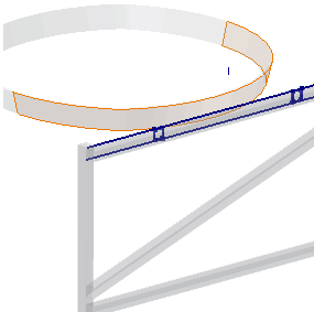
Finally, you create a left-hand and right-hand support to connect the frame to the strap. The supports use a derived construction surface as the termination surface for an extrusion.
- With the Frame subassembly active, create a component named SupportLeft in-place in the subassembly. Base the part on the Standard(mm).ipt template. Select the subassembly origin XY Plane as the initial sketch plane. Exit the initial sketch and delete Sketch1 to tidy up the browser.
- Derive the SkeletonBase part into the new part:
- Exclude all sketches other than SUPPORTS SKETCH from the derived part.
- Exclude Work Geometry and Parameters from the derived part.
- Expand Surface Bodies in the Derived Part dialog box.
- Exclude all surfaces other than Srf2 from the derived part.
- Click OK to complete the feature. Your assembly should match the one in the following image.

You might be asking why the separate strap surface is required. Why not create a solid body of the strap in the skeleton, and then derive the solid body as a solid or surface body into the support part?
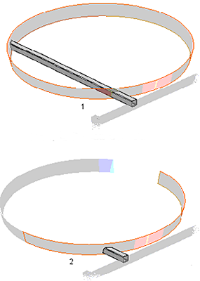
Notice that the strap surface feature is a single 180-degree revolved surface that matches the outer surface of the strap. The support tube profile will be extruded to this surface. If the termination surface provides more than one solution, the maximum termination is always the result. See the following image for an example.
You can choose a minimum or maximum solution for an extrusion termination.

1 - Extrude to 360 degree extrude strap
2 - Extrude to 180 degree extrude strap
- On the ribbon, click
3D Model tab
 Create panel
 Extrude
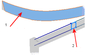
. Select the profile highlighted in the following image.
 - Click the Extents button flyout arrow in the Extrude mini-toolbar, and select To selected face/point.
- Click the derived surface highlighted in the following image.
- Click the More tab in the Extrude dialog box, and then select the Minimum Solution option.
- Click OK to complete the feature and close the Extrude dialog box.

1 - Extrude
2 - Profile
- Return to the Frame subassembly level, and then ground the SupportLeft part.
- Repeat the previous steps to create a right-hand support named SupportRight. Derive the same sketch and surface into the new part, and then extrude the other tube profile in the sketch to the termination surface. The Frame subassembly should match the one in the following image.
- Expand the derived SkeletonBase feature under the SupportLeft and SupportRight parts, and turn off the visibility of Srf2 to tidy up the Model browser.
