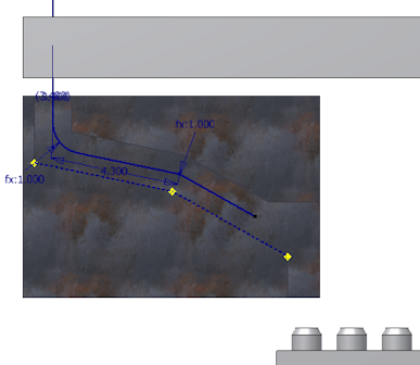
- Rotate your view to look at the front of the assembly. Tip: Click Right on the view cube to rotate the view to the desired position.
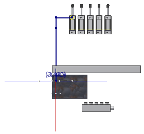
- Pause the cursor over the red direction axis of the 3D Orthogonal Route tool, right-click, and select Parallel With Edge.
The system prompts you to select a linear edge.
- Select the linear edge on the path part as shown in the following image, and click to set the selection.
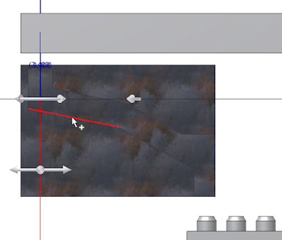
The red direction axis is reoriented to the direction of the selected edge. The included reference geometry is added to the Included Geometry folder in the Model browser.
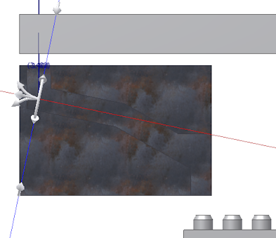
- Pause the cursor over the red axis, right-click, and select Enter Distance. Then enter 4.3 inch in the Enter Distance box, and then click the green check mark.
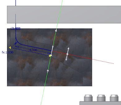
- Verify that a bend is automatically added between the new segment and the preceding segment.
- For the next point, right-click the red direction axis again and select Parallel With Edge.
- Select the other linear edge on the path part as shown in the following image.
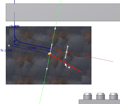
- Before creating the next route point, right-click in the graphics window and clear the Auto-Dimension check mark.
- Click anywhere in the forward direction on the red direction axis. The segment length is not important.
- Right-click in the graphics window and select Done.
- Verify that the new segment is not dimensioned.
