In this section, you place the slider assembly. A slider helps to release the plastic part by pulling the side core from the mold.
- On the ribbon, click Mold Assembly tab > Mold Assembly panel > Slider
 .
. - Orient the model as shown in the following image. The inserts and heels created for the side core are at the front of the view.
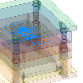
- On the Slider dialog box, review the preview image to understand the required references.
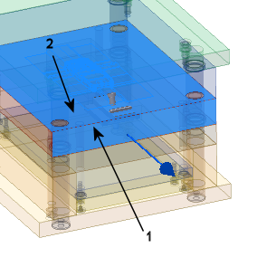
- Select the surface labeled 1 on the following image as the Pull Direction reference.
- Modify the Pull Direction Offset to -93 mm.
- Select the surface labeled 2 in the following image as the Base Plane reference.
- On the Slider dialog box, click Flip Side
 to flip the base plane orientation.
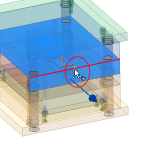
- Select the midpoint of the edge highlighted in the following image as the Base Point reference. When you move the mouse pointer near the center of this edge, it will automatically adjust to this point, and a yellow dot will appear in the display.
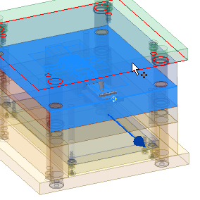
- Select the bottom surface of the top plate as the Pin Plane reference, as shown in the following image.
- On the Slider dialog box, click preview
 .
. - Rotate the model to view the bottom of the Slider assembly.
- On the Slider dialog box, click Side Core
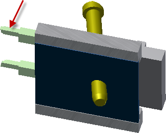
 . Select one of the two side cores (insert or heel features) as the Side Core reference, as shown in the following simplified image.
 You only need to select one of the inserts because they are both located the same distance away from the slider.
- On the Slider dialog box, click Update Travel
 .
. - At the top of the Slider dialog box, click Customize to modify the slider assembly parameters.
- From the Components list, select Angle Pin.
- On the right of the selected component, click Selection Properties
 .
. - Modify the AP_l parameter to 85 mm.
- Click OK on the Angle Pin dialog box.
- Modify the other components as shown in the following table.
Component Parameter Value Slider SL_b1 50 mm Slider SL_b2 59 mm Guide Strip (#1) SL_b1 50 mm Guide Strip (#1) GS_es1 10 mm Guide Strip (#2) SL_b1 50 mm Guide Strip (#2) GS_es1 10 mm Locking Heel LH_A 48 mm - On the Slider dialog box, click OK.
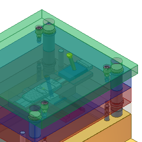
- Click OK on the File Naming dialog box to accept the defaults and place the slider.
- On the Quick Access toolbar, click Save to save the assembly.