In this section and the next, you place the lifter assemblies.
A lifter is an angled mold component that helps release undercut sections of the plastic part. The lifter is attached to the ejector plate and as the ejector plate moves forward, the lifter moves along an angled channel to release the undercut.
- On the Quick Access toolbar, click Design View > View1.
- On the Mold Design browser, right-click and click Visibility as required to match these settings:
- Plastic part (1) visibility enabled
- Workpiece, Core Cavity, Mold Base (2) visibility off
Orient the model as shown in the following image. View1 is needed for the selection of references in a later step.

- Click Design View > Default to return to the default design view.
- On the ribbon, click Mold Assembly tab > Mold Assembly panel > Lifter
 .
. - On the keyboard, press F6 to return to the Home View.
- The Select Pull Direction
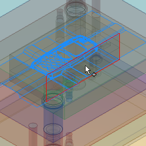
 tool should be active. Select the side of the workpiece, as shown in the following image.
- On the Quick Access toolbar, click Design View > View1.
- The Base Point
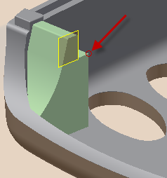
 tool should be active. Select the corner of the insert closest to the highlighted surface shown in the following image. Note: The image is simplified for clarity.
- Modify the following values in the Lifter dialog box:
- Pull Direction -7 mm
- Base Point -3.75 mm
- On the Lifter dialog box, click OK.
- Click OK on the File Naming dialog box to accept the defaults and place the lifter.
- On the Quick Access toolbar, click Save to save the assembly.