After you place a base view, the
Place Views tab
 Create panel
 Projected
![]() command is activated by default.
command is activated by default.
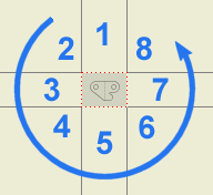
To understand your view projection options, move your cursor in a circle around the front view boundary without clicking. Notice that Autodesk Inventor previews eight different projected views. 

- Click below your front view to place a top view. Notice that a temporary rectangle is placed, indicating the intended location of the new view.
- Click to the right of your front view to place a left side view. Another temporary rectangle is placed.
- Click below your front view and to the right of your top view. A temporary rectangle is placed for an isometric view.
- Right click, and select Create. The three projected views that you positioned are now created.
Note: The ISO drafting standard specifies first-angle projection. The ANSI drafting standard specifies third-angle projection. Views are projected according to the standard specified by the template used to create drawings. Autodesk Inventor supplies templates for standards accepted world-wide. The supplied standards can be modified to suit your requirements.

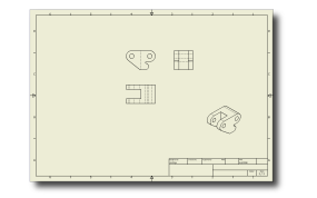
Approximate layout of current drawing sheet with one base view and three projected views. Moving views is easy, if necessary. Just click and drag a drawing view while the red dotted view boundary displays. Dependent views will position relative to the parent view.
At this point, you would likely begin adding dimensions to a simple part. However, for this part, add a section view.