- On the ribbon, click
Place Views tab
 Create panel
 Section
 .
. The Status Bar at the bottom left of the display screen prompts you to: Select a view or view sketch.
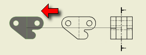
- Click the left side view located to the right of the front or base view on your drawing sheet.
You are prompted to enter the endpoints of the section line. Draw a vertical line that starts above the view geometry, extends below the view geometry, and passes through the middle of the part.
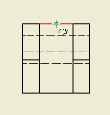
- To find the middle of the part, slowly move your cursor over the top-most line in the center portion of the part. When you reach the middle of that line, the cursor displays a green ball. Do not click yet!

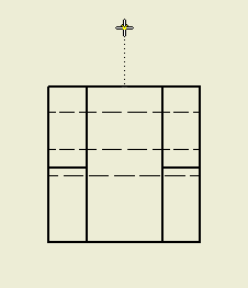
- Move your cursor slowly above the drawing view.

As you move upwards, notice the dotted line extending from your cursor to the middle of the part. This dotted line lets you know that you are aligned with the midpoint of the line that was located under the green ball. If you move too far to the right or the left as you move upwards, you are no longer aligned to that point, and the dotted line disappears.
- With the dotted vertical line visible, click to select the top-most point of the section line.
- Move your cursor straight down below the view. Your cursor indicates that the line is perpendicular to the part edge.

- While the perpendicular icon displays next to your cursor, click to select the end point of the section line.
- Right-click, and select Continue. The Section View dialog box appears offering various options for defining, identifying, and scaling the section view. For this exercise, accept the default settings.
- Move your cursor to the left of the front view, and click to place the section view and close the Section View dialog box.

During the creation of a section view, you can use Inventor ability to infer geometric relationships while you sketch your section line. In this example, you used a single, straight line. In other more complex cases, you will use a multi-segment line that passes through key points of multiple features.

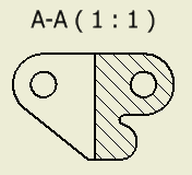
A section view is created, and a label is positioned that identifies the view and indicates the view scale. This view label is optional and can be repositioned and edited after placement as required.
- Move your cursor over the view label. When the label text changes to red, click and drag the label away from the view geometry to allow room for dimensions.
You will now place dimensions and other annotation on your drawing.