Create a custom component and transform it to an iPart factory. Then use the Tube and Pipe Authoring to set specific parameters for the iPart. After that, publish the iPart into a Content Center library.
You can also author and publish a part (not an iPart) as a fitting.
- Open the pipe.ipt iPart file from the Tutorial Files
 Tube & Pipe
  Example_iparts folder.
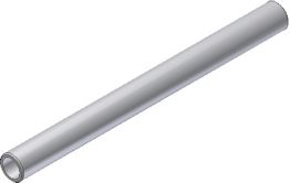
Optionally, right-click Table in the Model browser and select Edit Table to review the iPart parameters in iPart Author dialog box. Then close the dialog box.
- On the ribbon, click
Manage tab
 Author panel
 Tube and Pipe
.
  Tip: If needed, expand the drop-down menu to select Tube and Pipe Authoring.
 - In the Type list, select Pipes. The default value in the Connections list is 2 and cannot be modified.
- Verify that Connection Number 1 is selected to indicate that you are setting the information for Connection 1.
In the End Treatment list, select Welded.
- Click the red required fields, and select the attributes from the list as shown in the following image.
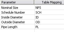 Note: The table defines mapping between attributes in the iPart table and required attributes of a part authored in the Pipes category.
 - Click Point if needed, and then select the connection point in the graphics window.
- Pause the cursor over the geometry until the circular edge is highlighted as shown.
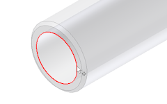
- Click to select the highlighted edge.
A connection point is displayed at the center of the circular edge.
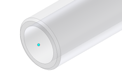
- Pause the cursor over the geometry until the circular edge is highlighted as shown.
- Click Axis in the Tube and Pipe Authoring dialog box, and then define the connection axis in the graphics window.
Pause the cursor over the same circular edge that you selected for the work point, and click to select. An arrow shows the axis direction.
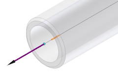 Tip: If the axis points toward the inside of the part, click Flip Direction. The connection direction must point toward the engaging fitting, so it often points outward.
 - Ensure Neutral connection is select. Neutral is automatically selected when the Welded end treatment is set.
- Specify the Engagement setting: Select Distance in the list. Confirm that 0 is set in Max and Min fields.Note: If the Engagement section is not available, a required setting was not yet set. Complete all previous settings first.Tip: When connecting pipe parts, the connection only applies to the engagement definition of the adjacent fittings by default. Any engagement parameters specified for a pipe iPart are ignored by default for the connection to the adjacent fittings. It is recommended that you set a fixed value of 0 in such cases.
The Connection Number 1 is now black, indicating that all connection criteria are satisfied for Connection 1.
- Click the Connection Number 2 to begin defining the second connection.
The parameter mapping is populated with information set for Connection 1. Since the nominal sizes are the same, no editing is needed.
- Set End Treatment to Welded.
- To define the connection information, click the circular edge on the other pipe end to set the connection point and connect axis.
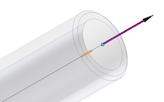 Note: For the Tubes, Pipes, and Hoses part types being authored, you do not have to specify the Pipe Length parameter for connections other than Connection 1. The Pipe Length parameter is unique for a conduit part.
 - Specify the Engagement setting: Select Distance and confirm that 0 is set in Max and Min fields.
- The Connection Number 1 and 2 are now black, indicating that all required connection criteria are set. Verify that all values are set properly.
Click OK to close the Tube & Pipe Authoring dialog box.
Then click OK on the Authoring Result dialog box.
- Save the authored pipe iPart and close the part file.
All authoring changes are saved for the next time you author the iPart again. You can publish the authored pipe to the Content Center.