Next we will export motion loads and run a stress simulation on a component. Use the following process for every component you want to analyze in the stress analysis environment.
Select the component
- Run the simulation.
- Open the Output Grapher.
- In the Output Grapher toolbar, click Export to FEA.
- In the simulation browser, select Follower:1 and click OK. The dialog box for selecting load bearing inputs is displayed.
Use the following process for each component you want to analyze in FEA:
Select faces
- In the graphics window, select the long shaft of the Follower component, which satisfies the prismatic joint input.
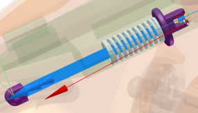
- In the dialog box, click Revolution 5.
- Select the small shaft that is used with the Follower Roller.
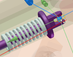
- In the dialog box, click the Spring joint.
- In the graphics window, click the face where the spring contacts the follower, and click OK.
Three joint inputs are required to satisfy the motion requirements for exporting the Follower component.
- Click the Deselect all command in the Output Grapher toolbar.
- Expand the Standard Joints, Revolution:5, and Force folders. Click Force.
- Expand the Force Joints, Spring / Damper / Jack joint, and Force folders. Click Force.
- In the graph region, double-click a Force (Revolution) graph high point you want to analyze. In the time steps section above the graph, place a check mark next to the corresponding time step.
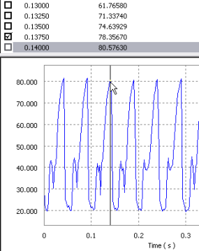
- Using the same method, select a low point of the Force (Revolution) values. Place a check mark next to its time step.
- Close the Output Grapher.
Next, specify the time steps to analyze:
Import into Autodesk Inventor Stress Analysis
- Click Finish Dynamic Simulation.
- On the Environments tab, click Stress Analysis to open in the Stress Analysis environment.
- In the Manage panel, click Create Simulation.
- In the dialog box, under Static Analysis, select the Motion Loads Analysis option. The two list controls below the option are enabled and populated with the exported parts and time steps.
- In the Part list, select the Follower component.
- In the Time Step list, select a time step to analyze.
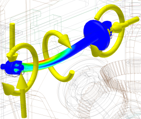
- Click OK. The assembly updates to represent that time step and then isolates the Follower component for analysis. You can observe symbols representing the various forces acting on the Follower.
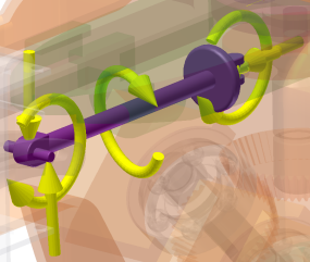
- Click Mesh Settings, then click Create Curved Mesh Elements.
- In the Solve panel, click Simulate, and then click Run. Wait for the simulation to complete.
- Select from the various Results data to see how the component performs at that time step.
- Click Finish Stress Analysis to exit the Stress Analysis environment.