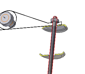
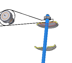
- Click Axis in the Placement region, and then select the cylindrical face of the valve.

- Select Start Plane. Orbit the assembly and select the start plane of the top retainer as shown on the image below.

A graphical preview of the compression spring displays in the Autodesk Inventor assembly.

A graphical preview of the selected geometry displays in Autodesk Inventor.
In the graphical preview of the compression spring, four types of grips are available:
- grips to specify the spring diameter
- grips to specify the wire diameter
- grip to move the spring along its axis
- grip to change the coils number
- To edit a value, drag or double-click the appropriate grip.
- On the Design tab, in the Placement region, select
 Min. Load from the drop-down menu.
Note: When you click the spring reference image at the top of the Design tab, a schematic image with the basic spring dimensions opens.
